By: Frank Rysanek of FCC Prumyslove systemy s.r.o., Czech Republic
e-mail: rysanek AT fccps DOT cz
This description: http://support.fccps.cz/download/adv/frr/pcl-839/pcl-839.html
Driver and library:
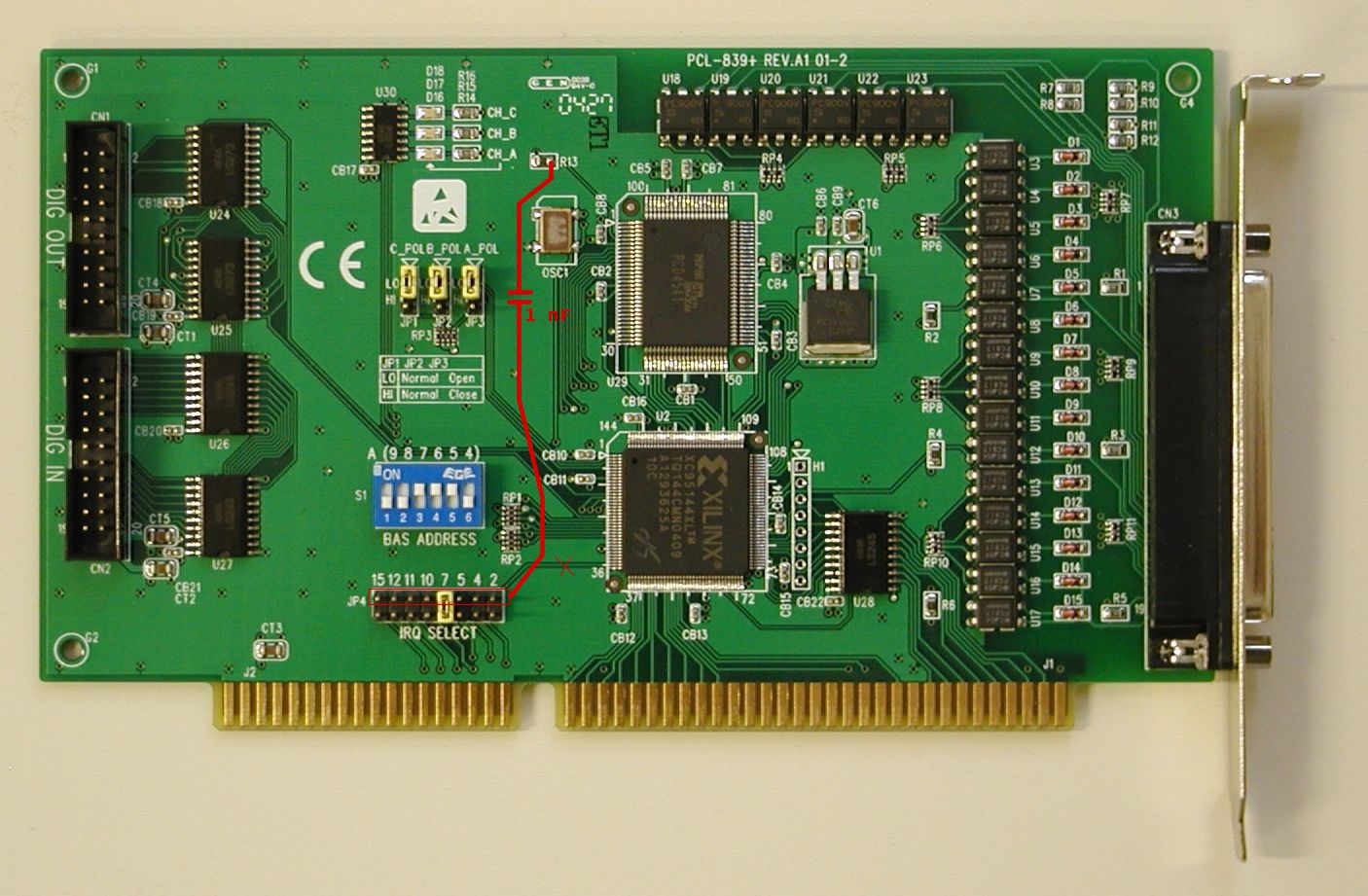
The Advantech PCL-839 and PCL-839+ are 3-axis motor control boards for the ISA bus, based on the Nippon Pulse Motor (NPM) PCL-AK and PCD4541 chips. 3 axis = 3 independent channels = 3 motors.
The boards are capable of the following, in hardware:
In addition, the PCD4541 chip is capable of the following (these features are not available on the PCL-839+, for the sake of backwards compatibility with the PCL-839):
In comparison to some other controller boards and IC's (namely the PCI-1240 containing a Nova MCX314), these features are missing:
The original PCL-839 was phased out suddenly in early summer of 2004, reportedly due to sudden shortage of its PCL-AK chip.
As a favor to regular customers among systems integrators, relying on regular supplies of the board, Advantech hastily launched the PCL-839+, announcing it to be backwards compatible with the former model (with only minor software modifications).
Along with the new PCL-839+, Advantech provided an updated board manual and a comparison sheet - unfortunately, it appears none of these were comprehensive enough. This HTML document should shed some light into some of the remaining dark corners. The information presented here was gathered from additional reading provided swiftly and kindly by Advantech (the PCD4541 chip manual) and by experiments while debugging the Linux driver (with an oscilloscope probe on the IRQ line).
The driver and library are rather thin wrappers around the PCL-839/PCL-839+ hardware functionality. To use this software package, the application programmer should know the PCL-839/PCL-839+ registers and semantics. This software package aims to shield away the application programmer from the low-level coding details of the PC/Linux platform, but not much more. The functions and macros provided by this package accept the speed/acceleration etc. values in their native hardware types and ranges, related to the underlying hardware registers, as described by the PCL-839/PCL-839+/PCD4541 manuals. I.e., there's no "math behind the scenes" as to convert the metric/physical values into the low-level hardware ranges and resolutions. This has to be done by the application (application programmer).
There are only a few areas in this software that provide some non-zero processing. These are usually related to the fact that the PCL-839/839+ per-axis configuration bits and status flags are mixed and multiplexed in various ways and thus somewhat cumbersome to work with in their native form. Let's have a few notable examples:
The basic PCL-839 functionality is handled by reasonably mnemonic wrapper functions and macros. The more advanced functionality, such as individual bits in the configuration registers, are only covered at the level of bare chip commands, symbolic bit names and inb/outb wrappers. The application programmer will have to study the PCL-839 manual and use these low-level functions and macros.
The software package described in this document consists of a driver in the form of a kernel-space module and a user-space library (for static or dynamic linking). The user-space library talks to the driver via a character device (opens an appropriate device node in the file system). The package is ready to work with multiple boards in the system, yet there's a single device node - multiple minor numbers would be more unix-like but perhaps unnecessarily complex to work with (depending on the particular real-world scenario at hand).
The header file is universal, all the function prototypes and macros work the same in kernel space and in user-space. In other words, the application programmer has freedom of choice, whether to compile the control application as a user-space executable binary, or as an insertable kernel-space module.
Obviously there are upsides and downsides to both kernel-space and user-space:
It's possible to strike a reasonable trade-off by splitting the application among kernel-space and user-space: timing-critical parts of the control task can run in a kernel module and the more relaxed parts can run as user-space apps, communicating among themselves from k-space to u-space via syscalls (read, write, ioctl) over device nodes (block or character type).
The driver and library attempt to present a single uniform interface for the two boards. The software is written primarily to suit the PCL-839+, which is the board currently manufactured and slightly more feature-rich. Where both cards support a particular feature in hardware, only mapped to different config/status bits or registers, the bit addresses are mangled behind the scenes for the PCL-839+. Functionality that's not supported by the PCL-839 hardware is not emulated in software. No range checking is done on register values (R0 through R7), but the bit-banging routines do return an error if an inappropriate bit is specified.
The header file contains a reasonable level of comments. If you're looking for a quick start, take a look at it.
The header file starts with mnemonic preprocessor macros (#defines) that substitute constant numeric identifiers of the various commands, registers, axis labels, IRQ source bits etc.
There are just a few core functions, implementing key parts of the functionality: read IO port, write IO port, issue a command, write a register, read a register etc. These in turn are used by a number of function-like wrapper macros, simplifying mnemonic access to the various PCL-839 registers.
As mentioned above, the set of functions and macros is the same in kernel-space and in user-space. The only exception is the pcl839_opendev() prototype that takes no argument in kernel space and one argument in user space (the device node filename).
The identical function prototypes are implemented differently in the kernel-space module and in the user-space library. Any functionality is really implemented only in the kernel variety, the user-space library consists of mere wrapper functions that pass the arguments to their kernel-space counterparts via ioctl(). The bunch of function-like macros only live in the header file (no implementation in the C files) - hence they work the same way in kernel space and in user space.
The elements of the header file are stacked vaguely like this:
| kernel space | user space | |
| macros | macros | |
| core functions | <=-. | core functions |
| outw,inw,kernel code | `- | ioctl() |
| hardware |
Except that, due to the inner dependencies of the header file, the contents flow from top to bottom, whereas the stack-style view above builds the layers from bottom to top.
In other words, in the header file, the most arcane functionality is located at the bottom. If you're after powerful macros and functions, try reading the header file from bottom to top :-)
For the named constants, take a look into the header file.
Functions:
int pcl839_opendev();            // kernel space
int pcl839_opendev(char* name);  // user space
int pcl839_closedev();

int pcl839_write_port(u8 board, u8 port, u8 data, u8 delay);
int pcl839_read_port(u8 board, u8 port, u8* data);
int pcl839_cmd_raw(u8 board, u8 axis, u8 cmd, u8 delay);
int pcl839_cmd(u8 board, u8 axis, u8 cmd, u8 delay);
int pcl839_status0(u8 board, u8 axis, u8* data);
int pcl839_write_reg(u8 board, u8 axis, u8 reg, u32 data, u8 delay);
int pcl839_read_reg(u8 board, u8 axis, u8 reg, u32* data);
int pcl839_write_IO(u8 board, u16 data);
int pcl839_read_IO(u8 board, u16* data);

int pcl839_wait4irq(u8 board, u32* data);

int pcl839_bang_bit(u8 board, u8 axis, u8 bit, u8 mode, u8 upload);
int pcl839_readback_bit(u8 board, u8 axis, u8 bit);
int pcl839_readback_reg(u8 board, u8 axis, u8 reg, u32* data);
Macros:
pcl839_start_stop_raw(board, axis, cmd, ramp_ena, use_fh, stop_irq_ena)
pcl839_start_stop(board, axis, cmd)
pcl839_start(board, axis)
pcl839_stop(board, axis)
pcl839_decel_stop(board, axis)

pcl839_reg_slct(board, axis, reg, delay)
pcl839_op_mode(board, axis, mode)
pcl839_out_mode(board, axis, mode)

pcl839_preset_pulse_count(board, axis, data, delay)
pcl839_fl(board, axis, data, delay)
pcl839_fh(board, axis, data, delay)
pcl839_acceleration(board, axis, data, delay)
pcl839_multiplier(board, axis, data, delay)
pcl839_rampdown_point(board, axis, data, delay)
pcl839_idling_pulse(board, axis, data, delay)
pcl839_output_type(board, axis, data, delay)
Compared to the PCD4541 manual, it's clear that most of the macros are mere shorthands for controller registers and commands. All of them really return an "int" error code (0 if success). For more information about the argument types and semantics, consult the comments in the header file and examples.
The PCD4541 manual is exhaustive but sometimes messy about the maths. Let's have a few things sorted out.
In this paper, wherever we speak of speed, we actually mean pulse rate, i.e. frequency (in Hz). Similarly, wherever we speak of distance or travel (abbreviated as "s"), we actually mean a total number of pulses (abbreviated as "p" or "P").
The sketches of ramps are plots of speed vs. time (i.e. not distance vs. time).
When ramping, the chip starts accelerating from an "initial speed" (V0) and accelerates up to the ultimate drive speed (V). The output then ticks at this ultimate speed (V), until the chip is told to decelerate (or decides to do that). Deceleration works vice versa.
During S-curve (quadratic) ramping, the acceleration is also variable. Each S-curve ramp consists of two parabolic (quadratic) areas. I.e., a whole accel/run/decel path contains four distinct parabolic areas. In each parabolic area, acceleration grows in a linear fashion (jerk is constant). I.e., acceleration is a derivative of speed, and jerk is a derivative of acceleration. One S-curve ramp is continuous in the second derivative, but the third derivative, called "jerk", is incontinuous just in the middle of the "S", where the speed has an inflexion point.
Let's distinguish between the machine units (register values) and the corresponding magnitudes used in general physics and mathematics.
Let's label the hardware values with capital letters:
M = multiplier
P = total pulse count (for preset pulse count operation)
V0 = initial speed (velocity) or pulse rate / frequency - the FL register
V = ultimate driving speed (velocity) or pulse rate / frequency - the FH register
A = acceleration (also used for deceleration)
Let's label the metric magnitudes (physical, SI, or whatever) with the corresponding lower-case letters - some of them are actual physical categories, some are not:
m = multiplier
s = p = distance traveled
v0 = initial speed
v = ultimate driving speed
a = acceleration
k = jerk
The application programmer will likely calculate with the real-world physical values.
The PCL-839/PCD4541 manuals provide a set of formulas to transform these into the machine values.
The following picture is a generic driving path plot (pulse rate vs. time) with S-curve acceleration and deceleration. Note the six regions (a through f) identified on the curve. The unlabeled seventh region in the middle is a constant speed area. Each region is goverened by its own mathematical function, though you may find useful analogies and shortcuts between a,c,d and f.
The PCL-839+ is only capable of "pure quadratic" S-curves, i.e. the commonly seen intermediate region of linear acceleration is not possible. Combined with a maximum acceleration that characterizes the particular electro-mechanical system being driven, this limits the total acceleration time achievable over an S-curve ramp. It's not possible to strike a tradeoff between the speed of a linear ramp and the smoothness of an S-curve. The quadratic-only S-curve is ultimately smooth but slow - given the upper bound on instantaneous acceleration, the S-curve takes twice the time of a linear ramp with the same acceleration.
The essential set of formulas is best demonstrated on region A and it should really look like this:
The blue area are the magnitudes as we know them (please substitute P for s). The green area are the formulas of how to arrive at them. Please note that the essential coefficient is the "jerk". The red area can be omitted - the PCL-839(+) is not capable of a "constant acceleration" component in this sense. On the other hand, the yellow area is VERY useful - the "constant speed" component is our initial speed (please substitute v0 for vc). The last component, sc, is an initial offset of our pulse count or travel - very obvious but hard to say how useful (that's really up to the application programmer).
Obviously the acceleration math applies analogically to the deceleration area.
The application programmer will likely work with plots of speed vs. time. Consequently, the starting formula is perhaps the third one: v(t) = 1/2 kt2 + vc. You know your initial speed, your terminal speed (beware, region A ends halfway between them!) and the time required to sweep from the former to the latter. Get the difference of speeds and divide by two. Divide the time difference by two. Enter that into this key formula and you get the jerk.
Let's have another graph. It'll demonstrate a simple trick that may simplify the math for the four parabolic regions.
The graph is a "unity curve" - regions A,C,D and F have duration of 1 s, their delta(v) is also equal to 1 P/s. There are no "constant accel/decel" regions (B and E) and the initial speed is a zero. Hence, this parabolic bell curve has only four regions. As described in the manual, using some simple math you'll find that
k = 2 P/s3
a(1) = 2 P/s2 = -a(3)
s(0,1) = 1/3 P
s(1,2) = 2 - 1/3 P
s(0,4) = 1/3 + 1 + 2/3 + 2/3 + 1 + 1/3 = 4 P
This gives some hints for the generic S-curve ramps involving nonzero constant acceleration regions.
Let's give up looking for shortcuts for the moment - let's go through all the math required for region "C", i.e. the upper end of the acceleration S-curve. Here's a simple sketch that will say more:
The red equation in upper left corner describes the upside-down parabola. Our region "C" is a part of it.
The last equation in the following set is a generic formula for the red square under that region (number of pulses between t2 and t3). The steps above it describe how it was arrived at. This is to say that only the last line matters - no need to go through all that symbolic math in software :-)
Try applying the values from the unity curve to verify that they fit the formula.
Another hint: try substituting a zero for t2 and (t3 - t2) for t3. Much simpler, is it :-)
Back to the PCL-839+ (PCD-4541) and its quadratic-only ramps. A single ramp consists of two parabolic areas, each with a different curve equation. There are two ways ways to derive the number of pulses (travel) within a ramp. Firstly, there's the symbolic method - let's combine the two curve equations for region A and C derived above, substituting a single delta t for t3 and t2 as suggested above:
Secondly, there's the graphical method that also makes use of the "unity curve" tricks:
And some formulas that can be identified in the sketch:
Thirdly, the PCD-4541 manual suggests the following formula, which also works, even though it's hard to transform to the ones above:
The PCD-4541 manual describes the math in limited detail on pages 22 through 24 (pages 34 through 36 of the PDF). The calculations are done straight in the machine units or, at the very best, there are conversion formulas given in a form where
real-world physics value = formula involving the machine value
which is perhaps not much use for the application programmer who needs to calculate the machine values from physical values in the first place to set up the controller. At the end of this chapter, the conversion formulas are listed in the inverted form.
The "velocity" here is a pulse rate (pulses per time), rather than a distance per time. Let's label the unit of one pulse with a capital "P". Let's use a slash "/" instead of the word "per". Thus, the unit of pulse rate (velocity) becomes 1 P/s (=1 Hz). The unit of acceleration will be 1 P/s2 (Hz/s). The unit of jerk will be 1 P/s3 (Hz/s2).
First, let's have the multiplier sorted out.
The nominal maximum output pulse rate of one PCL-AK axis is 16 kP/s. The external crystal ticks at 4.9152 MHz. Now the speed values are denominated in P/s, but the hardware registers are 16bit and only about 13 bits are effectively valid - the actual resolution of the speed values is 0 to 8000. So how do we reach those 16 kP/s?
Obviously there's some sort of a pre-scaler in the game. The coefficient here is called the "multiplier" (M), even though it's actually a divisor, inversely proportional to the theroetical multiplier "m". A value of 600 in the "MULTIPLIER" register actually means that indeed the FH and FL range of 0 - 8000 corresponds to 0 - 8000 P/s on the output. I.e., the physical " multiplier" is 1. The M register is inversely proportional to the multiplier, according to this formula:
      4915200          [Hz]
M = -----------
      8192 * m         [Hz?] [no unit]
The multiplier is clearly the first variable that needs to be sorted out, based on the required real-world values and hardware ranges of speed and acceleration. The speed registers (FL, FH) have a range of 0-8191, the acceleration register is limited to 0-1023.
The speed values are easy:
           v0         [P/s]
FL = V0 = ----
            m         [no unit]

           v          [P/s]
FH = V = -----
           m          [no unit]
It seems that the counting registers (the preset register and the ramp-down point register) are always in units of actual output pulses, no matter what the multiplier is.
The acceleration register is somewhat peculiar. The hardware value is inversely proportional to the physical acceleration intended:
    m * 4915200       [P/s]
A = -----------
         a            [P/s^2]
Please note that the range of the ACCEL register is 1-1023 (10 bits). Thus, the actual minimum acceleration in "1x mode" (M == 600, m == 1) is about 5 kHz/s. Combined with a maximum pulse rate of 16 kHz, this is barely enough to be noticeable on a 'scope.
With the PCL-839+, the physical magnitude called "jerk" is kept quite implicit - it's never mentioned in the manual. The slope of an S-curve ramp is influenced by the "ACCELERATION" register - the value entered is actually derived from the peak instantaneous acceleration (happens in the inflexion point halfway up the ramp), the conversion formula is the one above, the same as for linear ramps.
It can be easily proven that with the same values in FL, FH and ACCEL registers, a quadratic ramp takes twice the time of a linear ramp, and the S-curve's peak acceleration is the same as the linear curve's characteristic constant acceleration (i.e., its average acceleration is one half the value of a linear ramp).
Linear ramp:
    v - v0       [P/s]
t = ------
      a          [P/s^2]
S-curve ramp:
        v - v0       [P/s]
t = 2 * ------
        a(max)       [P/s^2]
Interestingly, during S-curve ramping, the minimum acceleration rate of 5 kHz/s only applies to the value set in the ACCEL register - it does not influence the instantaneous acceleration rate of the actual S-curve. In other words, the S-curve is not clipped to fit the range of the ACCEL register, and the S-curve ramp does take twice as long even with the ACCEL register set to 1023.
The implicit value of "jerk" can be extracted in several ways, e.g.:
The following table is a more elaborate superset of the original Advantech feature comparison sheet.
| PCL-839 | PCL-839+ | Comment | |
| General data | |||
| Controller chip | 3x PCL-AK | PCD4541 | Both by Nippon Pulse Motor co. (NPM) |
| Max. pulse count | +/- 262134 18 bits |
+/- 16777215 24 bits |
Resolution of the preset register (R0) - can be multiplied in software |
| Max. pulse rate | 16 kPps (kHz) | 200 kPps (kHz) | The resolution of FL and FH is still 13 bits => higher multipliers |
| Register functions | |||
| Preset pulse cnt. | R0 (18b) | R0 (24b) | Once set, this register keeps counting down to zero. |
| FL | R1 (13b) | R1 (13b) | Initial velocity, V0 |
| FH | R2 (13b) | R2 (13b) | Terminal velocity, V |
| ACCEL | R4 (10b) | R3 (10b) | 1/ Acceleration (linear ramp) or peak acceleration (S-curve) |
| MULTIPLIER | R7 (10b) | R4 (10b) | 1/ Multiplier coefficient (== actually a divider) |
| Ramp-down point | R6 (16b) | R5 (16b) | Start decelerating when preset_reg < this |
| Idling pulse | N/A | R6 (3b) | Some motors need this to wake up from stand by? |
| Output mode | N/A | R7 (1b) | Pulse+dir vs. up+down - single bit, R7.0 |
| Register read/write | |||
| Register write sequence |
Register select Write lo byte Write hi byte |
Register select Write hi byte Write mid byte Write lo byte Delay 400 ns |
Byte order is important |
| Register read sequence |
Register select Read lo byte Read hi byte |
Register select Delay 300 ns Read byte Read byte Read byte |
Byte order is unimportant |
| Configuration bits | |||
| ~FL/FH | Start_Stop.0 | Start_Stop.0 | 0 = use FL speed, 1 = use FH speed |
| ~Int.Start/Ext.Start | N/A ? | (Start_Stop.1) | 1 = inhibit start command, wait for the ~STA signal |
| Ramping enable | Start_Stop.2 | Start_Stop.2 | 0 = constant speed operation, 1 = "high speed" (==ramping) |
| Stop Bit | Start_Stop.3 | Start_Stop.3 | start bit + stop bit = decel stop |
| Start Bit | Start_Stop.4 | Start_Stop.4 | start bit + stop bit = decel stop |
| Stop int enable | Start_Stop.4 | Start_Stop.4 | 0 = mask, 1 = unmask/enable |
| ORG enable | Op_Mode.0 | Op_Mode.0 | 0 = ignore ORG signal, 1 = respond to ORG (origin return) |
| SD enable | Op_Mode.1 | Op_Mode.1 | 0 = ignore SD signal, 1 = respond to SD (slow down) |
| Preset mode enable | Op_Mode.2 | Op_Mode.2 | 0 = continuous mode, 1 = preset mode) |
| Reverse direction | Op_Mode.3 | Op_Mode.3 | 0 = count up, 1 = count down) |
| OTS (gen.purp.out) | N/A ? | (Op_Mode.4) | OTS signal output pin - used e.g. to enable motor drive |
| ~Linear/Sigmoid | N/A ? | (Op_Mode.5) | 0 = linear ramping, 1 = sigmoid ramping |
| Preset cntdn inh | Out_Mode.2 | Reg_Slct.3 | 0 = normal operation, 1 = prevent preset register from counting down |
| Rampdown int ena | Reg_Slct.4 | Reg_Slct.4 | 0 = mask, 1 = unmask/enable |
| Ext.sta.int ena | N/A ? | (Reg_Slct.5) | 0 = mask, 1 = unmask/enable |
| Output ~neg/pos | Reg_Slct.5 | Out_Mode.0 | 0 = pulse output logic negative, 1 = positive |
| Pulse out inh. | Reg_Slct.3 | Out_Mode.1 | 0 = normal operation, 1 = inhibit pulses on output |
| Exc.seq.inh. | N/A ? | (Out_Mode.2) | 0 = normal operation, 1 = inhibit excitation sequencer output |
| Ramping inh. | Out_Mode.4? | Out_Mode.3 | 0 = normal ramping, 1 = lock current speed in the middle of accel/decel |
| Glitch suppress | Out_Mode.5 | Out_Mode.4 | 0 = raw, 1 = glitch suppression on ORG, EL, STP |
| Ext.mon.ena | N/A ? | Out_Mode.5 | 0 = off, 1 = extended monitor on (more status regs) |
| ~Up+Dn/Pls+Dir | Out_Mode.1 | R7.0 (inv?) | 0 = Up+Down, 1 = Pulse+Direction |
| Man.Rampdown | Out_Mode.3 | N/A ? | 0 = manual setting of ramp-down point, 1 = auto ramp-down |
The most important difference/novelty that didn't make it to the Advantech documentation with the new PCL-839+, is the mandatory delay upon register read/write transactions and the mandatory descending byte order upon register write. See also these errata against the shipping PCL-839+ manual: write sequence.
Reportedly the original PCL-839 defaulted to pulse+dir, whereas the new PCL-839+ defaults to up+down (R7.0).
The ORG/EL/SD wiring schematic featured in the PCL-839+ manual is slightly wrong(EL+/EL- are swapped). The wiring schematic contained in the original PCL-839 manual is correct, only the left-to-right orientation of the drawing is mirrored in comparison to all PCL-839+/PCD-4541 material.
The onboard output pull-up of the PCL-839+ is rather weak - consider adding a stronger external pullup even when coupling the output to high-impedance inputs, to prevent potential adverse effect of the cabling's parasitic capacity.
The IRQ's are almost omitted in the Advantech PCL-839/839+ manuals, and barely described enough in the PCL-AK and PCD-4541 manuals. There are some documentation discrepancies, and some sweet secrets that have simply fallen below the radar screen as far as the manuals are concerned.
Yet the IRQ's do work and it's appropriate to use them if at all possible. It's not that complicated. The driver attempts to simplify IRQ handling.
First of all, obviously it is perfectly possible to use the board without IRQ's. I.e., some application software would simply write a new speed value and re-issue a start command every once in a while, based on an OS-based timer. In that case, the application programmer doesn't have to care about the peculiarities of IRQ handling on the board - just keep all the IRQ sources masked and you're fine.
On the PCL-839/PCL-839+ you can observe these IC's:
The motor controller IC's are almost native ISA IC's, but their access to the actual host system's ISA is mediated/interfered with by the CPLD. Both the motor controller(s) and the CPLD seem to be involved in IRQ handling.
The IRQ's generated by the motor controllers are originally level-triggered. As long as the interrupt source is active, the IRQ line sticks to the active level (low). The CPLD converts this to an edge-triggered IRQ, for the sake of compliance with the host ISA bus and the XT-PIC.
On the PCL-839, the three INT lines from the controller chips are OR'ed by the CPLD into a single ISA IRQ line. Consequently, the CPLD presents three status bits (one per axis) in the board-global IRQ status register.
On the PCL-839+, the motor controller already presents a single IRQ line to the CPLD, and the CPLD applies a single-shot gate to produce a signal suitable for the ISA IRQ line. Consequently, the CPLD only reports a single status bit for the whole board.
The driver deploys a generic ISR that aims to take a reasonable action in response to any IRQ that may occur - specifically, it properly ACKs (=masks) both ramp-down and "stop" interrupts. All the application programmer has to do is use the wait_for_irq() function. See also the IRQ handler in pcl-839.c.
In addition to the board-global IRQ status register, the motor controller chip provides two or three IRQ status bits per axis, all of them in one register (S1 on the PCL-839, S0 on the PCL-839+), mixed with other status bits that are not IRQ related. The OR'ed product of these sources per axis shows up as a single bit in another register (S0 on the PCL-839, S2 on the PCL-839+).
Clearly, the IRQ status bits are interspersed with other useful data in the controller chip's internal registers. Moreover, to check the status of the individual IRQ sources, on the original PCL-839 you even have to issue a register select (two ISA IO transactins, two CPU instructions) to access the respective internal register - caveat, if you're using arbitrary (timer-based) access to the board's registers from your software outside the ISR, you may face clashes of this unsuspecting code with the register select done by the ISR!
Speaking about the board-global IRQ status register, implemented by Advantech using a CPLD, beware: you'd better forget about it, it doesn't work the way it should. On a PCL-839, it lags behind - it always shows the status that applies to the previous IRQ event. On a PCL-839+, the IRQ status bit is always a one - no use in shared IRQ scenarios.
There's more. At least on a PCL-839+, it has been observed that the per-source IRQ status bits (as read from S0) don't follow the manual! Both the PCL-839+ board-level manual and the PCD4541 chip-level manual say that S0.0 = stop int, S0.1 = ramp-down int, S0.2 = ext.start int. In reality, a rampdown int yields 0x05 in the last three bits, whereas a stop int yields 0x01 or 0x06. I.e., the three bits seem to return some sort of an enumerated result code, rather than a bit per IRQ source as the manuals would put it. Yet the IRQ masking bits do work and must be toggled as documented.
Which brings about the very interesting subject of IRQ masking and ACKing on these boards.
While the interrupt generating condition is true, its respective interrupt source is active, and so are the respective status flags - there's no automagic "ack upon read". The interrupt source becomes inactive only when the trigger condition ceases to be true anymore.
Hence, to prevent repeated ISR invocation, you have to mask the respective interrupt source within the ISR, and perhaps leave it up to the rest of the software to talk to the controller IC and re-enable the interrupt source only when appropriate.
The board-global IRQ enable bit in the CPLD need not be fiddled with at runtime - it is only toggled once at program startup, to enable interrupt generation globally for the whole board. The repetitive ACKing/masking is done using the per-axis/per-source masking bits.
There's another peculiarity: the INT enable/disable bits are not a part of some regular register - they are a part of two important executive commands. Hence, you can't set/clear the "stop interrupt enable" bit without re-issuing a start/stop command, and you can't toggle the "ramp-down interrupt enable" bit without issuing another "register select" command.
Fortunately this means that the masking bits are tightly coupled to the commands that they'll likely be a part of - so this arrangement does make sense, even though it appears to decrease general programming transparency of the chip.
Still, the driver aims to assist in the bit-banging involved - all register writes are cached, so the application programmer doesn't have to keep track of all the bits when sending simple commands to the board.
A note on polarity: the IRQ signals generated by the motor controllers are active-low. Perhaps that's why the on-chip detailed IRQ source flags are also active-low (negative logic). The IRQ enabling bits use positive logic - set the bit to 0 to mask the IRQ source, set it to 1 to enable the IRQ. The board-global IRQ enable&status register appears to use positive logic (except when impaired by the issues mentined above.)
If you need to mix non-trivial IRQ handling with timer-driven register updates on a PCL-839, consider enclosing the "register select + value access" combo transactions in a pair of spin_lock_irqsave() and spin_lock_irqrestore(), that effectively provide mutual exclusion in the critical section - using the sti and cli instructions on the local processor. Which may however impair interrupt handling performance on the machine - even on today's multi-GHz processors, no IRQ can be served until the two to four ISA IO instructions are finished, with ISA running at 8 MHz.
Please note that this performance impact is not dependent on the frequency of IRQ's from the PCL-839 boards, but on the frequency of your benign "register select" transactions done by non-ISR threads! I.e., the total amount of machine time spent with IRQ disabled will be proportional to the frequency of your motor control software's loop timer, to the number of register access transactions performed within the loop, and to the number of processes or threads running in the loop. If only the ISR could do without "register select's"!
At a first sight, the spinlock is perhaps not necessary for a PCL-839+ (no register access is necessary in the IRQ), where it would cause yet more IRQ performance impact, due to the mandatory 400ns/300ns timeout upon register write/read.
Please note that the spinlock is perhaps not required for IRQ ACKing, as the "register select" needed to ACK a ramp-down interrupt can be re-issued from a "cache" to point to the same register - not sure if this is true for the PCL-839+ though, again due to the mandatory timeouts after the register select... perhaps another good practice would be to avoid the ramp-down interrupt alltogether.
SMP and HyperThreading could somewhat alleviate the impact of the spinlock discussed above. There is PC hardware capable of both ISA and HT and even SMP (dual Xeon). Just consider the potential waste of CPU horsepower and electricity.
The driver doesn't implement the spinlock discussed above. Add one into the kernel module if you need it.
To save yourself the spinlocking headache discussed above, consider these tips:
The ISA IRQ's are typically edge-triggered, activated by a rising edge. Surprisingly, each IRQ line appears to have a pull-up to logical 1 (+5V) on the motherboard - IRQ sharing would benefit from an opposite edge polarity or opposite pull-up. Once an interrupt is processed by the ISR and acked to the XT-PIC (in Linux this ACK is done by the master handler), the PIC does not re-trigger the ISR even if the IRQ line stays put in logical 1.
When handling an interrupt, each of the two boards behaves in a somewhat different way.
The PCL-839 leaves the IRQ line floating normally high (due to the pull-up), and only generates a narrow negative spike (1 us or so) upon the interrupt - its open-collector output closes for a short instant and lets go again. This behavior would be suitable for IRQ sharing - multiple PCL-839 boards could take turns in flashing the IRQ line. Then again, the pulse is only generated when the event has occurred - and it starts with a falling edge. Hence, the rising edge, that is decisive for the host PC's PIC, is delayed against the original event by the duration of the pulse, which is a bit of a deficiency.
In contrast, the PCL-839+ holds the IRQ line normally low, and only generates a positive pulse upon an interrupt. Its open-collector line driver (or is it a full totem pole?) only lets go when an interrupt event occurs - hence it's no problem that the pulse is significantly wider. Thus, the rising edge is well aligned to the interrupt generating event - but the positive logic is unsuitable for IRQ sharing.
Therefore, arguably, the PCL-839+ doesn't support ISA IRQ sharing (whereas the PCL-839 theoretically does). And, obviously, multiple PCL-839 and PCL-839+ don't mix well on a single IRQ line.
There are two possible imperfect workarounds for the PCL-839+:
This is to say that, even if the Advantech boards are "successfully" forced to coexist on a single IRQ line, one substantial problem persists: there is a risk of lost IRQ's, if IRQ pulses coming from multiple boards overlap in time. In that case, the two edge-triggered interrupts become one, and quite possibly the second one will stay unserved until another interrupt occurs (and this time the ISR flushes the unACK'ed board). This is not a fault on part of Advantech, this is a generic issue of the ISA bus!
This train of thought would perhaps lead to a "serializing OR gate". Except that quite possibly this counting gate would have to obtain explicit ACK's (would have to be assigned an I/O address on the ISA bus, and occupy an ISA slot), so that effectively it would become yet another interrupt controller in the host machine...
Please note that PCI's level IRQ's are designed to prevent lost interrupts. And, modern PC's have APIC's, that are aimed to enhance the number of IRQ lines available in the machine, which lowers the order of IRQ sharing.
On the ISA bus, even if it's not possible to re-program the XT-PIC to use level IRQ's, perhaps it would be possible to let the machine boot into APIC mode, let the kernel route the APIC interrupts, and then re-program the already known APIC input pins for level IRQ's. Obviously this is only possible on machines equipped with APIC's and ISA - in general these are Pentium4-based industrial CPU cards and perhaps some PentiumIII SMP machines (few of them equipped with any ISA slots).
To put it another way:
As a side note, if you're considering some real-time Linux extensions such as RTAI, it's a shame that e.g. the popular Intel 845 chipset family is reported to exhibit high and random IRQ latencies... On the other hand, who's ever seen a CPU board with e.g. the SiS 651? Perhaps some Intel 865/875 and above perform better. In every other aspect, all Intel chipset based hardware is rock-solid, well-behaved, stable and powerful.