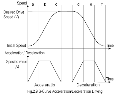
(This graph is taken from the MCX314 manual.)
By: Frank Rysanek of FCC Prumyslove systemy s.r.o., Czech Republic
e-mail: rysanek AT fccps.cz
This description: http://support.fccps.cz/download/adv/frr/pci-1240/pci-1240.html
Driver and library: http://support.fccps.cz/download/adv/frr/pci-1240/pci-1240-1.0.tgz
The Advantech PCI-1240 is a 4-axis motor control board for the PCI bus, based on the Nova Electronics MCX314 chip. 4 axis = 4 independent channels = 4 motors.
It is capable of the following, in hardware:
The PCI-1240 driver and library are rather thin wrappers around the MCX-314 hardware functionality. To use this software package, the application programmer should know the PCI-1240/MCX314 registers and semantics. This software package aims to shield away the application programmer from the low-level coding details of the PC/Linux platform, but not much more. The functions and macros provided by this package accept the speed/acceleration/jerk etc. values in their native hardware types and ranges, related to the underlying hardware registers, as described by the MCX314 manual. I.e., there's no "math behind the scenes" as to convert the metric/physical values into the low-level hardware ranges and resolutions. This has to be done by the application (application programmer).
There are only a few areas in this software that provide some non-zero processing. These are usually related to the fact that the MCX314 per-axis registers are mixed and multiplexed in various ways and thus somewhat cumbersome to work with in their native form. Let's have a few notable examples:
The basic MCX314 functionality is handled by reasonably mnemonic wrapper functions and macros. The more advanced functionality, such as individual bits in the configuration registers and the whole interpolation area, are only covered at the level of bare MCX314 commands and inw/outw wrappers. The application programmer will have to study the MCX314 manual and use these low-level functions and macros.
The software package described in this document consists of a driver in the form of a kernel-space module and a user-space library (for static or dynamic linking). The user-space library talks to the driver via a character device (opens an appropriate device node in the file system). The package is ready to work with multiple boards in the system, yet there's a single device node - multiple minor numbers would be more unix-like but perhaps unnecessarily complex to work with (depending on the particular real-world scenario at hand).
The header file is universal, all the function prototypes and macros work the same in kernel space and in user-space. In other words, the application programmer has freedom of choice, whether to compile the control application as a user-space executable binary, or as an insertable kernel-space module.
Obviously there are upsides and downsides to both kernel-space and user-space:
It's possible to strike a reasonable trade-off by splitting the application among kernel-space and user-space: timing-critical parts of the control task can run in a kernel module and the more relaxed parts can run as user-space apps, communicating among themselves from k-space to u-space via syscalls (read, write, ioctl) over device nodes (block or character type).
The header file contains a reasonable level of comments. If you're looking for a quick start, take a look at it.
The header file starts with mnemonic preprocessor macros (#defines) that substitute constant numeric identifiers of the various commands, registers, axis labels, IRQ source bits etc.
There are just a few core functions, implementing key parts of the functionality: out word, in word, 16bit write command, 32bit write command, 16bit read command, 32bit read command etc. These in turn are used by a number of function-like wrapper macros, simplifying mnemonic access to the various MCX314 registers.
As mentioned above, the set of functions and macros is the same in kernel-space and in user-space. The only exception is the pci1240_opendev() prototype that takes no argument in kernel space and one argument in user space (the device node filename).
The identical function prototypes are implemented differently in the kernel-space module and in the user-space library. Any functionality is really implemented only in the kernel variety, the user-space library consists of mere wrapper functions that pass the arguments to their kernel-space counterparts via ioctl(). The bunch of function-like macros only live in the header file (no implementation in the C files) - hence they work the same way in kernel space and in user space.
The elements of the header file are stacked vaguely like this:
| kernel space | user space | |
| macros | macros | |
| core functions | <=-. | core functions |
| outw,inw,kernel code | `- | ioctl() |
| hardware |
Except that, due to the inner dependencies of the header file, the contents flow from top to bottom, whereas the stack-style view above builds the layers from bottom to top.
In other words, in the header file, the most arcane functionality is located at the bottom. If you're after powerful macros and functions, try reading the header file from bottom to top :-)
For the named constants, take a look into the header file.
Functions:
int pci1240_opendev();            // kernel
int pci1240_opendev(char* name);  // user-space
int pci1240_closedev();

int pci1240_writel_cmd(u8 board, u8 channels, u8 cmd, u8 delay, u32 data);
int pci1240_writew_cmd(u8 board, u8 channels, u8 cmd, u8 delay, u16 data);
int pci1240_readl_cmd(u8 board, u8 channels, u8 cmd, u8 delay, u32* data);
int pci1240_readw_cmd(u8 board, u8 channels, u8 cmd, u8 delay, u16* data);
int pci1240_exe_cmd(u8 board, u8 channels, u8 cmd, u8 delay);
int pci1240_outw(u8 board, u8 offset, u8 delay, u16 data);
int pci1240_inw(u8 board, u8 offset, u8 delay, u16* data);

int pci1240_wait4irq(u8 board, u32* data);

int pci1240_bang_bits(u8 board, u8 channels, u8 reg, u8 mode, u16 data);
int pci1240_readback(u8 board, u8 channels, u8 reg, u16* data);
Macros:
pci1240_set_range(board, channels, delay, data)
pci1240_set_jerk(board, channels, delay, data)
pci1240_set_accel(board, channels, delay, data)
pci1240_set_decel(board, channels, delay, data)
pci1240_set_init_speed(board, channels, delay, data)
pci1240_set_drv_speed(board, channels, delay, data)
pci1240_set_pulse_cnt(board, channels, delay, data)
pci1240_set_decel_pnt(board, channels, delay, data)
pci1240_set_circ_centr(board, channels, delay, data)
pci1240_set_log_pos(board, channels, delay, data)
pci1240_set_real_pos(board, channels, delay, data)
pci1240_set_comp_pos(board, channels, delay, data)
pci1240_set_comp_neg(board, channels, delay, data)
pci1240_set_accel_ofs(board, channels, delay, data)
pci1240_axis_select(board, channels, delay)

pci1240_get_log_pos(board, channels, delay, data)
pci1240_get_real_pos(board, channels, delay, data)
pci1240_get_cur_speed(board, channels, delay, data)
pci1240_get_cur_accel(board, channels, delay, data)

pci1240_start_puls_pos(board, channels, delay)
pci1240_start_puls_neg(board, channels, delay)
pci1240_start_cont_pos(board, channels, delay)
pci1240_start_cont_neg(board, channels, delay)
pci1240_start_hold(board, channels, delay)
pci1240_sthold_rel(board, channels, delay)
pci1240_stop_decel(board, channels, delay)
pci1240_stop_now(board, channels, delay)
pci1240_interp_2d_lin(board, channels, delay)
pci1240_interp_3d_lin(board, channels, delay)
pci1240_interp_cw_cir(board, channels, delay)
pci1240_interp_ccw_cir(board, channels, delay)
pci1240_interp_2d_bit(board, channels, delay)
pci1240_interp_3d_bit(board, channels, delay)
pci1240_bp_write_allow(board, channels, delay)
pci1240_bp_write_deny(board, channels, delay)
pci1240_bp_data_stack(board, channels, delay)
pci1240_bp_data_clear(board, channels, delay)
pci1240_interp_1step(board, channels, delay)
pci1240_decel_valid(board, channels, delay)
pci1240_decel_invalid(board, channels, delay)
pci1240_interp_int_clr(board, channels, delay)

pci1240_write_irq_mask(board, channels, data)
pci1240_set_irq_mask(board, channels, data)
pci1240_clear_irq_mask(board, channels, data)

pci1240_reset(board, delay)
Compared to the MCX314 manual, it's clear that all the macros except the last four are mere shorthands for the controller commands. All of them really return an "int" error code (0 if success). For more information about the argument types and semantics, consult the comments in the header file and examples.
The MCX314 manual is somewhat cryptic about the maths. The results are OK, but the procedure to arrive at them is sparse and the notation is often incorrect. A slightly less cryptic reinterpretation follows.
In this paper, wherever we speak of speed, we actually mean pulse rate. Similarly, wherever we speak of distance or travel (abbreviated as "s"), we actually mean a total number of pulses (abbreviated as "p" or "P").
The sketches of ramps are plots of speed vs. time (i.e. not distance vs. time).
When ramping, the chip starts accelerating from an "initial speed" (SV) and accelerates up to the ultimate drive speed (V). The otput then ticks at this ultimate speed (V), until the chip is told to decelerate (or decides to do that). Deceleration works vice versa.
During S-curve (quadratic) ramping, the acceleration is also variable. Each S-curve ramp consists of two parabolic (quadratic) areas. I.e., a whole accel/run/decel path contains four distinct parabolic areas. In each parabolic area, acceleration grows in a linear fashion (jerk is constant). I.e., acceleration is a derivative of speed, and jerk is a derivative of acceleration. One S-curve ramp is continuous in the second derivative (the third derivative, called "jerk", is incontinuous just in the middle of the "S", where the speed has an inflexion point.
Upon quadratic ramping, the "acceleration" (and deceleration) values mean upper bounds - if the chip reaches this bound before the inflexion point, it keeps accelerating at this maximum rate. As a result, there's a larger linear area in the middle of the "S".
In compliance to the manual, the hardware values are labeled with capital letters:
R = range
P = total pulse count (for fixed pulse count operation)
SV = initial speed or pulse rate (starting velocity)
V = ultimate driving speed or pulse rate (velocity)
A = acceleration
D = deceleration
K = "jerk" - a first derivative (slope) of acceleration for S-curve ramping
Let's label the metric magnitudes (physical, SI, or whatever) with the corresponding lower-case letters - some of them are actual physical categories, some are not:
m = multiplier
s = p = distance traveled
sv = initial speed
v = ultimate driving speed
a = acceleration
d = deceleration
k = jerk
The application programmer will likely calculate with the real-world physical values.
The MCX314 provides a set of formulas to transform these into the machine values.
On page 7 of the MCX314 manual (page 12 of the PDF file), there are some nice curve plots and also an attempt to explain the basic maths. There are two formulas, saying that v(t) = at2 and that p(t) = 1/3 at3. This is almost correct - you only have to replace the "a" with "1/2 k" (and forget about the constant bits, coming out of the generic integration).
The following picture is a plot of a generic driving path (pulse rate vs. time) with S-curve acceleration and deceleration. Note the six regions (a through f) identified on the curve. The unlabeled seventh region in the middle is a constant speed area. Each region is goverened by its own mathematical function, though you may find useful analogies and shortcuts between a,c,d and f.

(This graph is taken from the MCX314 manual.)
The essential set of formulas is best demonstrated on region A and it should really look like this:
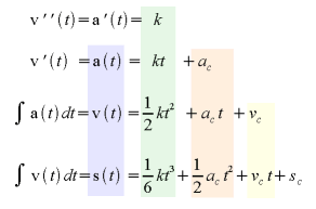
The blue area are the magnitudes as we know them (please substitute P for s). The green area are the formulas of how to arrive at them. Please note that the essential coefficient is the "jerk". The red area can be omitted - the MCX314 is not capable of a "constant acceleration" component in this sense(the A and D are mere upper bounds on a(t) and d(t)). On the other hand, the yellow area is VERY useful - the "constant speed" component is our initial speed (please substitute SV for Vc). The last component, Sc, is an initial offset of our pulse count or travel - very obvious but hard to say how useful (that's really up to the application programmer).
Obviously the acceleration math applies analogically to the deceleration area.
The application programmer will likely work with plots of speed vs. time. Consequently, the starting formula is perhaps the third one: v(t) = 1/2 kt^2 + Vc. You know your initial speed, your terminal speed (beware, region A ends halfway between them!) and the time required to sweep from the former to the latter. Get the difference of speeds and divide by two. Divide the time difference by two. Enter that into this key formula and you get the jerk. If you want to skip the "constant acceleration" regions (B and E), set the accel and decel bound parameters to be higher than the calculated a(t) or d(t) that will be reached in the center point, halfway through the acceleration or deceleration.
Let's have another graph. It'll demonstrate a simple trick that may simplify the math for the four parabolic regions.
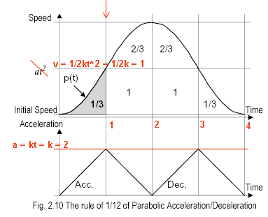
(This graph is taken from the MCX314 manual. Excuse the corrections.)
The graph is a "unity curve" - regions A,C,D and F have duration of 1 s, their delta(v) is also equal to 1 P/s. There are no "constant accel/decel" regions (B and E) and the initial speed is a zero. Hence, this parabolic bell curve has only four regions. As described in the manual, using some simple math you'll find that
k = 2 P/s3
a(1) = 2 P/s2 = -a(3)
s(0,1) = 1/3 P
s(1,2) = 2 - 1/3 P
s(0,4) = 1/3 + 1 + 2/3 + 2/3 + 1 + 1/3 = 4 P
This gives some hints for the generic S-curve ramps involving nonzero constant acceleration regions.
As a final touch, let's give up looking for shortcuts for the moment - let's go through all the math required for region "C", i.e. the upper end of the acceleration S-curve. Here's a simple sketch that will say more:
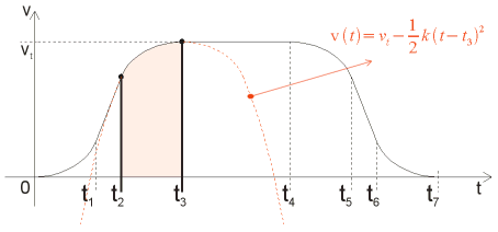
The red equation in upper left corner describes the upside-down parabola. Our region "C" is a part of it.
The last equation in the following set is a generic formula for the red square under that region (number of pulses between t2 and t3). The steps above it describe how it was arrived at. This is to say that only the last line matters - no need to go through all that symbolic math in software :-)
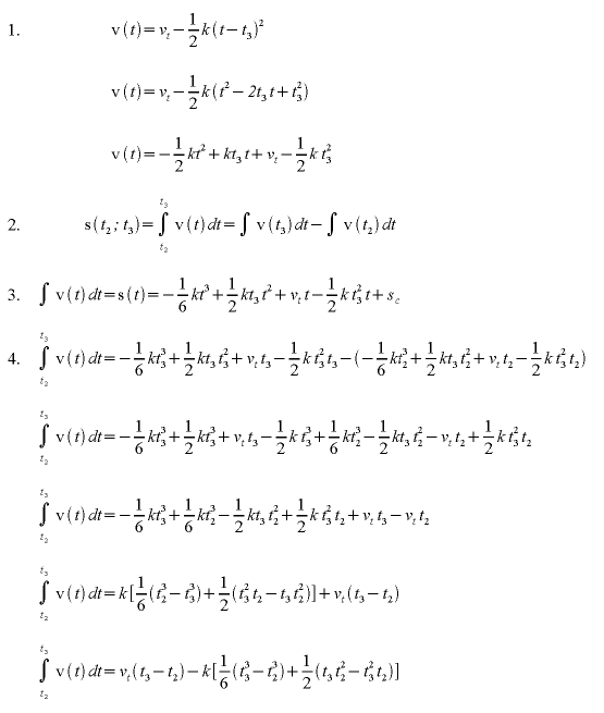
Try applying the values from the unity curve to verify that they fit the formula.
Another hint: try substituting a zero for t2 and (t3 - t2) for t3. Much simpler, is it :-)
The MCX314 manual summarizes the conversion math on page 51 (page 56 of the PDF). The formulas are given in a form where
real-world physics value = formula involving the machine value
which is perhaps not much use for the application programmer who needs to calculate the machine values in the first place, to set up the controller (before he can read back actual real-time values). At the end of this chapter, the conversion formulas are listed in the inverted form.
The "velocity" here is a pulse rate (pulses per time), rather than a distance per time. Let's label the unit of one pulse with a capital "P". Let's use a slash "/" instead of the word "per". Thus, the unit of pulse rate (velocity) becomes 1 P/s. The unit of acceleration will be 1 P/s2. The unit of jerk will be 1 P/s3.
First, let's have the multiplier/range sorted out.
The nominal maximum output pulse rate of one MCX314 axis is 4 MP/s. The external crystal ticks at 16 MHz, but the internal master clock is divided by two, i.e. 8 MHz. Now the speed values are denominated in P/s, but the hardware registers are 16bit and only about 13 bits are effectively valid - the actual resolution of the speed values is 0 to 8000. So how do we reach those 4 MP/s?
Obviously there's some sort of a pre-scaler in the game. The coefficient here is called the "range" (R). A range of 8,000,000 (the default value) means that indeed the V and VS range of 0 - 8000 corresponds to 0 - 8000 P/s on the output. I.e., the " multiplier" is 1. The range is inversely proportional to the multiplier, according to this formula:
     8 000 000
R = -----------
         m         [no unit]
The multiplier is clearly the first variable that needs to be sorted out, based on the required real-world values and hardware ranges of speed, accel/decel and jerk. The manual is not completely clear about the jerk range: somewhere it says 0-64k, somewhere it says 0-8000. The speed and accel/decel hardware values (S,SV,A,D) are limited to 0-8000.
The speed values are easy:
      sv         [P/s]
SV = ----
       m         [no unit]

      v         [P/s]
V = -----
      m         [no unit]
The acceleration/deceleration values are easy, too. They need to be divided by an additional constant of 125.
        a          [P/s^2]
A = ---------
     125 * m       [no unit]


        d          [P/s^2]
D = ---------
     125 * m       [no unit]
The jerk value is somewhat cursed. K is inversely proportional to the physical jerk, and the coefficient is weird - nevertheless, the formula works:
      62.5 * 10^6 * m         [no unit]
K = ------------------
            k                 [P/s^3]
On the PCI-1240 you can observe three IC's:
All the three IC's seem to be involved in IRQ handling. To find out more about IRQ handling on this board, take a look at the IRQ handler and its comments in pci-1240.c.
The MCX314 and the Xilinx are on an ISA bus, attached/mapped to the host PCI bus via the PCI9052. In other words, the MCX314 is not directly interfaced to the PCI. Hopefully, owing to the low-rate nature of this IC, the applications won't suffer from the fact that the data transfer performance feels more like a poor ISA design, rather than a swift PCI. If you want to know more about this ISA-to-PCI relay, see the the PCI9052 manual and get a dump of its memory space (see the PCI init routine in the pci-1240.c).
The pulse rates (speeds) are set as multiples of pulse per second. Hence, at a first sight it would seem that the MCX314 has a PLL-based frequency synthesizer per channel - operating perhaps above 1000 Hz (1000 is the ratio between the maximum range and the basic resolution of the speed values).
Based on one note in the MCX314 manual, this is probably not true. According to the manual, only speeds that are integer fractions of the master clock (8 MHz) are completely precise. Of course, other speeds are synthesized too, and a counter-based meter will find them precise - it's just that they have an aliasing jitter of up to +/- 1 clock tick. It seems that the chip employs some sort of a bivalent divider to achieve that dithering effect. It makes sense - a PLL-based pulse generator for this range would be difficult to implement and would suffer from leading glitches or slow starts (until the PLL feedback loop settles), which is a problem in this application.
The jitter gets more significant towards the high end of the output pulse range spectrum. The MCX314 manual assures that this aliasing jitter is filtered by the motor's mechanical inertia and hence doesn't have any practical influence.