A rare close-range picture and video, showing upward leaders growing to meet the branching downward leader.
(source publication, raw slo-mo video data)
This HOWTO was inspired by a debate at a Meinberg
agents meeting earlier this year.
Hence the Meinberg antennas in some of the pictures, and hence the focus on antenna placement,
protection and small-signal coax cabling.
Note that I am not a Meinberg employee, I've merely been a techsupport for their hardware
for two decades or so, in a "regional agent company".
In a legal sense, I do not speak for Meinberg.
I am neither a licensed engineer in the business of lightning protection,
nor in fact an EE graduate. From a professional perspective, I'm a hobbyist
with 20 years of practice on jobs in neighboring areas.
If you'd appreciate professional advice for your particular circumstances,
or a second opinion, by all means do contact a licensed lightning protection
practitioner in your area / in your application field.
For quality reading, refer to the IEC/EN 62305 norm, and/or official
documentation by Dehn or other vendors of relevant surge arrestors
and other lightning protection hardware.
In most countries, any installations related to lightning safety, especially on the outside
lightning protection system of a building, are subject to official inspection/approval,
and should be designed by a licensed project engineer.
Lightning safety serves to protect human lives and to prevent damage to property.
Let's skip all theory and jump headlong to the key question:
Q: If my antenna has a "protective earth" terminal, or just an exposed chassis ground, maybe at some mounting bolts:
Should I ground the antenna right where it is mounted?
Should I avoid that? If yes ground it, then where to?
Is the outside Lightning Protection System the perfect ground node for this purpose?
A: It depends :-)
Depends on your application circumstances. On your building / vessel / vehicle. On your geographical location.
Me being an inland guy with brick and mortar buildings all around, I tend to say "Almost definitely not.
By default, keep your antenna away from the outside LPS!"
People with other backgrounds may vigorously disagree :-)
To some people, a hefty PE terminal on the antenna can be a blessing.
To me in my typical circumstances, that same PE terminal is redundant, and possibly a trap for the unwary.
Caveat, emptor :-)
Perhaps the correct advice, carefully worded might be: "the chassis of the antenna
should be grounded, but not to the outside LPS. If you insist on grounding your antenna,
find or implement a solid ground that is not your outside LPS.
If in doubt, strive for equal potentials in your signal chain."
I will try to elaborate on that in examples throughout this howto.
In the following text, I'll try to explain things and give examples, preferably using lots of pictures.
I'll try to give credit where credit is due, and warn about ideas that are my own
(and therefore require a pinch of salt).
Some places may get thicker in theory, I may even flash a formula or two
- but you can always skip the more arcane bits.
While I technically do have access to the EN 62305 (Czech mutation), there's an online resource that I find more useful / richer in examples: I will refer to it as the Dehn Bible - officially the Lightning Protection Guide. And there's more - just see the references.
Fasten your seatbelts.
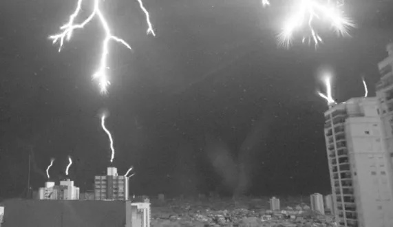
Lightning is a divine natural spectacle.
Owing to modern slow-motion cameras and YouTube, we can get perspective of how the descending arc finds its way through the stormy sky.
The followinng pictures are thumbnails - click them to continue to YouTube for a video. As some of the videos are lengthy, I try to link to a particular time, where an interesting lightning develops. Obviously feel free to rewind as you see fit.
A rare close-range picture and video, showing upward leaders growing to meet the branching downward leader.
(source publication, raw slo-mo video data)
A difference of potentials worth up to hundreds of millions of Volts accumulates in the atmosphere,
and finds a way though the storm clouds to discharge itself into ground, via a beautiful branching
jagged arc.
The arc does not flash into existence all at once,
it "crawls" at a finite velocity, or rather, takes a sequence of short jumps.
This effect, apart from being visually appealing, should also help us understand
some of the "best practices", tools and lore of modern Ligtning Protection System design.
In the picture and video above, it's interesting to note how the tips of the "leaders" get dragged by corona (the publication speaks in detail about "streamers" = individual "rays" in the corona). The corona seems to siphon charge from local "pockets of lower resistance", and provides enough energy (current) for the developing channel to stay ionized = conductive.
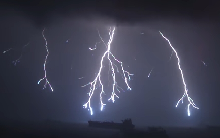
Footage by the Slow Mo Guys - thunderstorm at the sea in Singapore
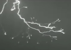
YT vid by Robert Patterson, containing a snippet of footage from National Geographic
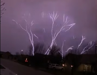
A YT short published by StoryfulNews, showing an amazing upward lightning strike in Kansas
There's more on YouTube, these are just a few examples.
Apparently, lightning bolts are typically negative and growing downward in the characteristic branching fashion, but in rare cases the atmosphere is positively charged, in that case the lightning grows upward, and consequently (?) the branching leader is not observable from the ground. Some sources just say that positive lightnings are not branching... There's a whole science and taxonomy on the topic.
Points to remember from this chapter:
The concepts presented in this chapter, in no particular order, are codified in norms:
IEC/EN 62305 part 2/3/4, and also others, outside of the IEC62305 family.
I will try to order the topics to follow up on each other, and refer to the canon
where suitable.
The IEC/EN 62305 has inherited many concepts from its predecessor norms.
Among them, the breakdown of space into so-called Lightning Protection Zones.
That's a nice meme to start with :-)
The zones are numbered by their level of lightning strike hazard: 0, 1, 2.
Lightning protection zones and common ground
For the LPZ's to be valid and functional in their protection stratification,
the building must be equipped with a plausible Lightning Protection System, aka LPS.
The LPS shorthand typically refers to the outside LPS, meaning the air termination (collectors),
the downconductors, and the lightning-current-capable outside earth termination (grounding).
In addition to the outside LPS, for the LP zones to be properly delimited,
the building must also have a working inner system of Protective Earth,
and any wiring that crosses a boundary between LPZ's, must be protected
at the LPZ boundary by suitable "arrestors" - as a general rule, arrestors
are grounded to the internal PE distribution of the building.
By default, the outside LPS is for direct-hit lightning current only.
This is because, while it can withstand and safely conduct away the direct
lightning strike (current), in so doing, it tends to develop dangerous voltage levels.
There's a related concept of "safe separation distance" (from the outside LPS)
that we will explain in more detail a little bit later. Advance hint: "safe separation"
is what normally prevents you from grounding antennas and the first arrestor (= type 1)
to the outside LPS.
The LPZ's are nowadays codified in the IEC/EN 62305-4 (building-internal protection).
A key concept and component, to the integrated lightning and overvoltage protection in a building,
is common ground. The outside LPS must be interconnected with the inner tree of PE distribution,
at a very particular and well defined place: at the base of the building = at terrain level,
by a conductor going from the outside LPS ground to the inner central PE node of the building.
As a minor, tangential and not so important side note, please mind the difference between a PE and
a working return ground in the mains distribution inside a building. And yes these two are joined
together as well, at the exact same inner central busbar at the base of the building. (A separate
yellow-green PE does not exist outside of a building.)
The star-shaped splitting of inner ground (both PE and N = common/return) is traditionally arranged using busbars, in various sizes, shapes and forms.
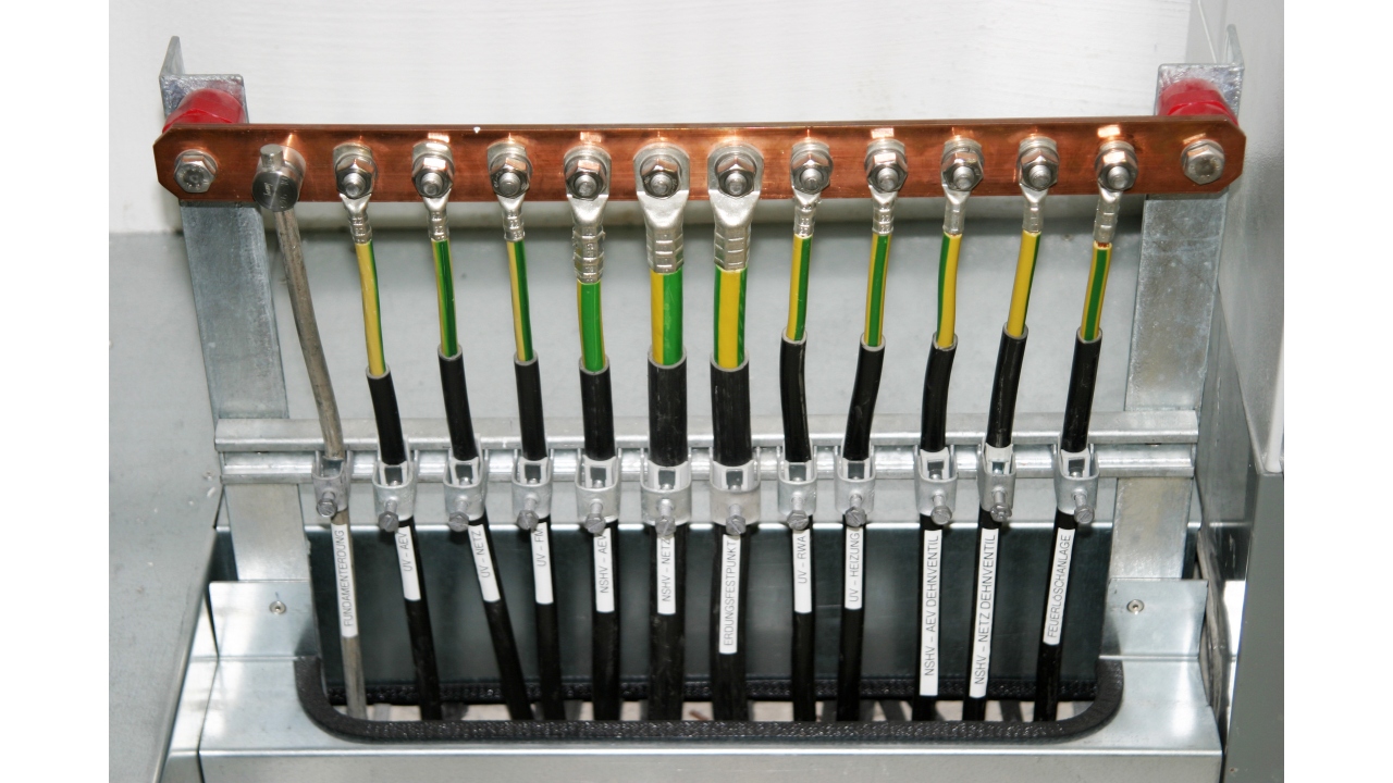
A larger busbar by Dehn
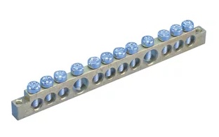
A smaller busbar by nVent
In principle, a busbar is just a metal bar with screw terminals,
suitable as a central interconnect point for wires
arriving and departing in various directions.
There are various sorts, either for stand-alone use,
or as an internal accessory for mounting inside
plastic circuit breaker boxes etc.
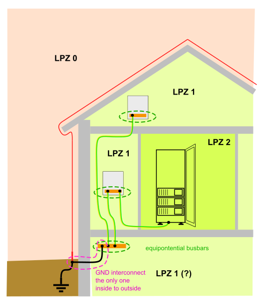
The word "equipotential" does not refer to a particular construction arrangement. It refers to function in the block schematic: "serving the equalization of potentials".
The "wiring" aspect of equipotential bonding is codified as part of IEC 60364-4-41 and IEC 60364-5-54. Lightning protection aspects are detailed in IEC/EN 62305-3 (external protection) and 62305-4 (internal protection).
Equal potentials of the Protective Earth, i.e. a common reference ground,
is a key concept in surge protection. The systemic protection approach hinges on this.
Equal potentials for every exposed earth inside the house.
Only connected to the outside LPS ground at about the terrain level.
Thus, if a lightning strikes the outside LPS, this one combined common ground
in the basement does still jump up (due to earth resistance),
but the whole house "jumps up and settles down en bloc",
so that no harm (injury / fire hazard) is done to anything and anyone
inside the house, as long as any outgoing/incoming wiring is "clamped"
by surge-arrestors to this single PE potential within the house.
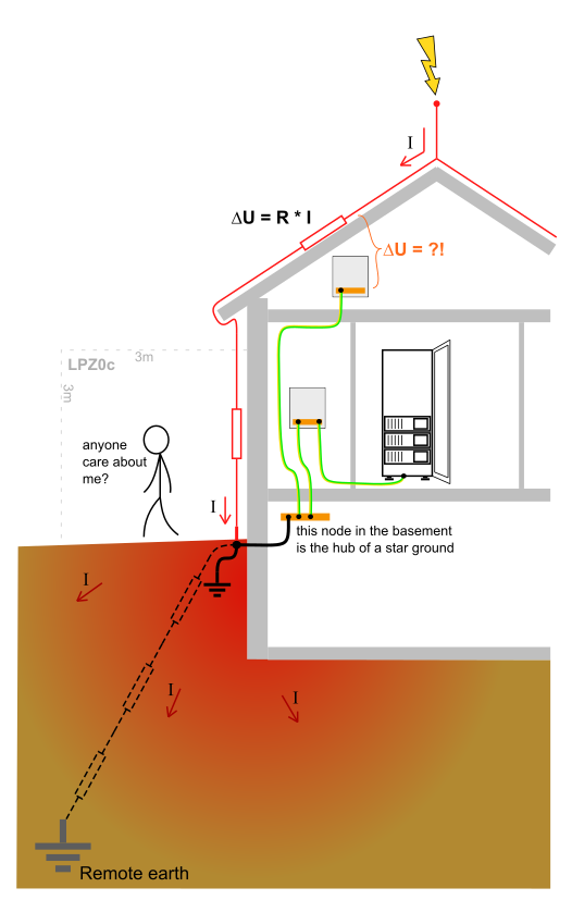
Ohmic concerns in the outside Lightning Protection System
(The cryptic reference to LPZ0c will be clarified later, together with LPZ0a/b.)
This picture is an attempt to draw attention to resistive behavior of the outside LPS, and also of the underlying earth (geology).
To get some sense of the ballpark, let's start with some practical numbers that we're dealing with here.
The peak current of a lightning strike, with a 99% confidence,
is specified to be below 100 - 200 kA, depending on
Lightning Protection Level (AKA LPS class).
There are 4 LPL's = LPS classes, depending on detailed risk assesment.
Read: think of what happens at 100 - 200 kA, considering the resistances
outlined below.
This initial peak may have a half-life of a millisecond or so, but more follows and it can take several seconds for the ionized channel to die completely. (Typically it dies in a fraction of a second.)
| Metal | Resistivity ρ [Ω·m] | Ω/m, 16 mm2 | Ω/m, 50 mm2 | Ω/m, 100 mm2 |
| Copper | 1.68 · 10-8 | 1.05 · 10-3 | 0.34 · 10-3 | 0.17 · 10-3 |
| Aluminium | 2.65 · 10-8 | 1.66 · 10-3 | 0.53 · 10-3 | 0.27 · 10-3 |
| Iron | 9.70 · 10-8 | 6.06 · 10-3 | 1.94 · 10-3 | 0.97 · 10-3 |
| Stainless steel* | 69.0 · 10-8 | 43.1 · 10-3 | 13.8 · 10-3 | 6.9 · 10-3 |
Imagine a small house, with two down-conductors, 10m each,
made of 50 mm2 zinc-galvanized steel (iron).
Combined, that's about 10 milliOhms from the tip of the
lightning rod to the earth termination system's attachment clamp.
If I recall correctly some comments from an inspector at our
premises the other day, such a value would be a miracle,
unless all the joints are welded. But let's take this optimistic value.
Ignoring inductance, the resistive voltage drop
would be 2 kV peak for a 200 kA lightning strike.
The IEC/EN 62305 mandates minimal conductor cross-sections for the LPS, and minimal counts / maximal spacing of down-conductors along the perimeter of the building.
The minimal "safe bet" cross-section is 16 mm2 copper.
For the lower Lightning Protection Levels (LPS classes),
Aluminum and even steel are theoretically okay too,
at 16 mm2.
Stainless steel is not suitable at 16 mm2 cross section,
for the down-conductor role.
It is interesting to note that 16 mm2 of copper is worth the same as
100 mm2 of steel, resistance-wise. It would appear that a "plausible maximum"
for conductor resistance might be about 1 milliOhm per meter of length,
but the primary problem is not residual voltage. The primary concern is heat-up
by the lightning current. Standard steel at 16 mm2 at 200 kA in LPS class 1
would melt. Therefore, apart from resistivity, mass and melting temperature
are other factors. We could try some math with energy, thermal capacity
and melting point, but ahh well... let's just trust the norm on this.
There's a neat table in the Dehn Bible on page 97.
Downconductor spacing is on page 95.
So much for the outside LPS, its cross-sections and materials.
Time to take a short look at the ballpark of grounding ("earth termination").
Various types of "earth" (geological materials) have very different typical values
of resistivity (ρ) and quoted in relatively broad brackets.
For practical design purposes, earth resistivity
can be measured on site, there are tools and methods for that.
Let's have a few values to get a coarse idea:
| Material | Resistivity ρ [Ω·m] |
| Sea water | 0.3 |
| Swamp | 5 - 40 |
| River/lake water | 10 - 100 |
| Dirt/clay | 20 - 200 |
| Humid sandy soil | 200 - 400 |
| Concrete | 150 - 500 |
| Dry sandy soil | 1000 - 2000 |
| Rocky soil | 100 - 3000 |
| Gravel/sand | 2000 - 3000 |
| Weathered rock | < 1000 |
| Sandstone | 2000 - 3000 |
| Granite | up to 50 000 |
Although the Dehn Bible mentions some formulas for ballparking
the earth electrode resistance for different constructions
of the electrode, it's still kind of difficult to get your hands
on a practical number.
In the Dehn Bible on page 128 (ish), there is a chart or two,
showing values of RE for several values of earth
resistivity. For ρ between 100 and 400, and a grounding
conductor (electrode) buried in a length of 10 m, the resulting
resistance was somewhere in double digit Ohms.
Times something like 100 kA, ho hum...
Note that this is referring to earth termination. In a building with
a properly interconnected system of LPS earth and inner PE GND,
and with arrestors in place, people and hardware in the building
are pretty much safe. But, upon a lightning strike, the earth
resistance translates into a gradient of voltage in soil
around the building (earth termination) which can be dangerous.
This is called a step or stride voltage.
We'll probably revisit this sub-topic briefly when debating
earth termination around large buildings and in substations.
The following animated picture is a little tangential in our context.
Considering what's been said so far, guess what may arrive at the ends
of the communication link between the two houses. Mind the arrestors
at the signal cable's entry point into each building, and think about their role.
Protection of communication links in general

Statistical lightning density across Germany, average 1999-2011
Scale: <0.6 .. <3.0 strikes to earth per km2 per year
Source: found on page 34 of the Dehn Bible
Original source: Siemens Blitz-Informations-Dienst
Appears closely related to a domestic German supplement No.1 to IEC/EN 62305-2.
The statistical density of strikes is a key factor in risk assessment
and Lightning Protection Level categorization. The "Lightning Protection Level"
seems synonymous with "Lightning Protection System class".
The IEC/EN 62305 dedicates a whole part 2 (i.e. "62305-2") to risk management.
A rich topic in its own right - let's call it out of scope in this howto :-)
You may want to check chapter 3 in the Dehn Bible.
Suffice to say, that the LPS class is an important intermediate variable,
used as a parameter in various rules in Lightning Protection System design,
as per IEC/EN 62305-3.
| Lightning Protection Level (Ligtning Protection System class) |
I | II | III | IV |
| Max peak lightning current / statistical confidence |
200 kA / 99 % | 150 kA / 98 % | 100 kA / 95 % | 100 kA / 95 % |
| Min peak lightning current [1] / statistical confidence |
3 kA / 99 % | 5 kA / 97 % | 10 kA / 91 % | 16 kA / 84 % |
| Rolling sphere radius | 20 m | 30 m | 45 m | 60 m |
| Cone α for h=20m [2] | 22° | 39° | 49° | 55° |
| Building height for cone α=22° [2] | 20 m | 30 m | 45 m | 60 m |
| Mesh size (grid spacing)[3] | 5 x 5 m | 10 x 10 m | 15 x 15 m | 20 x 20 m |
| Spacing of downconductors | 10 m | 10 m | 15 m | 20 m |
| Safe separation ki | 0.08 | 0.06 | 0.04 | 0.04 |
While the table above mostly deals with LPS design parameters
that are off topic in this howto, the rows highlighted by blue background
are relevant to anyone who needs to place an antenna.
These values give you a clue, how far the "shade" under the air
termination reaches - also known as the LPZ0b, see the next chapter.
If unsure what your LPS class is at a particular site,
be careful = brace for the worse case.
Time to introduce the distinction between LPZ0a and LPZ0b, using the older cone method and the newer rolling sphere method.
The LPZ0 = outside space, gets further subdivided into three flavours:
To define the reach or coverage of LPZ0b, there are two methods: the older cone method and the newer rolling sphere method. See the two pictures below.
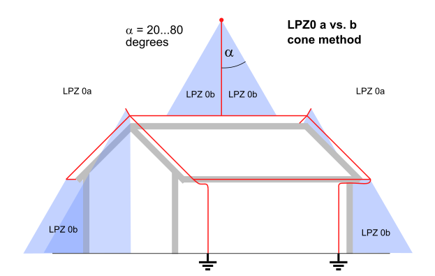
LPZ0b using the older cone method
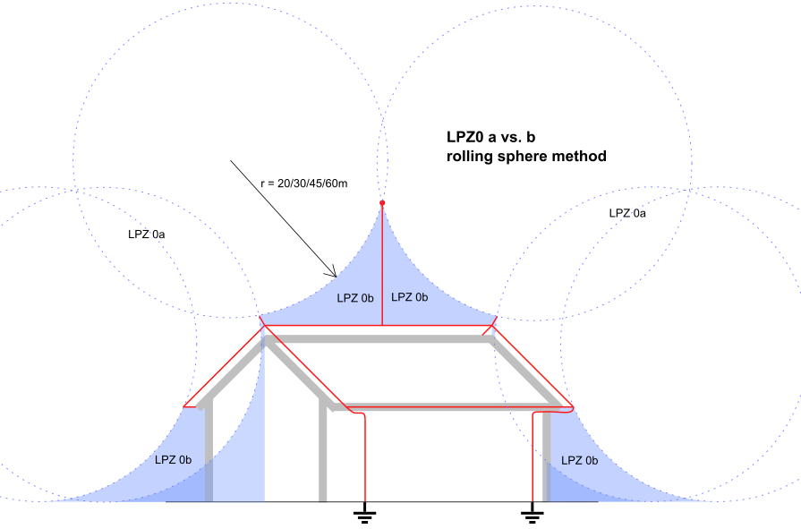
LPZ0b using the modern rolling sphere method
There is one other general concept, that I haven't mentioned yet:
safe separation distance.
I have kept it under wraps until this point,
to demonstrate it on a more practical example.
It's exactly the requirement for "safe separation" that's in irreconcilable opposition to
"grounding an antenna to the outside LPS". A nuanced explanation follows.
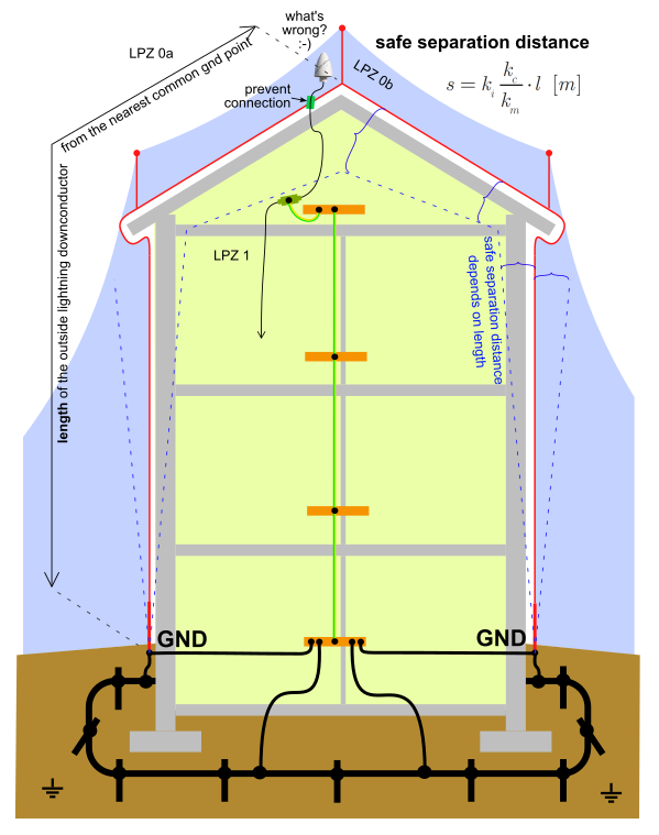
A tall brick and mortar building, including an explanation of separation distance
Q: Can I ground the antenna to the outside LPS?
A: Absolutely not! Read on for details (separation distance).
What's wrong with the antenna? Well in 2D, it doesn't heed
the separation distance sketched in that same picture :-)
Which will be explained below.
Safe separation distance means, how far away from the outside LPS it is safe to place...
whatever it is that needs to stay out of harm's way. Such as, an antenna on the roof,
or stuff inside the building.
The point is, that the outside LPS itself becomes live during a lightning strike.
The downconductors have a resistance, which means that gentlemen Ohm and Kirchhoff
attend the party thrown by Mr. Ampere, giving rise to some ugly Volts as a product
of the lightning current. Worse yet, the LPS also has an own
inductance, which means that Mr. Henry tends to steal
center stage for a few microseconds right at the start, where he merrily
launches the unpopular Mr. Volta through the ceiling...
producing an ugly voltage pulse, corresponding to the leading edge of the
lightning current, where the Δi/Δt is the steepest.
The canonical/codified formula to calculate safe separation distance seems largely "empirical".
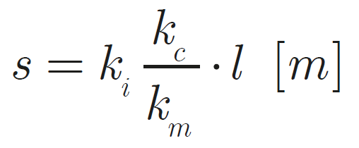
It incorporates a combination of three coefficients:
Looking at the ballparks of the three k's, we can try estimating
the approximate ballpark of the overall coefficient:
10 cm of separation distance per 1 m of downconductor length?
Sounds about right... I've actually seen examples where the number turns
out lower, within a decimal order. Those were not examples for tall
buildings, exposed radio towers on mountaintops, ships cruising high seas etc.
In the Dehn Bible, you'll find "safe separation" detailed on pages 150 - 156.
I have one other concept that I decided to show in this example:
what an "earth termination" often looks like. It typically consists
of metal conductors, round or flat at the cross section, buried in the earth.
Typically combined (interconnected) with vertical rods rammed deeper in the earth
at regular distances. Construction details get determined by a licensed
design engineer and are a part of the construction project documentation.
In my practical observation, at least a loop of flat zinc-plated steel conductor
(say 30x4 mm) gets buried around a family home, connected to the vertical
downcondutors and inner PE.
Stainless steel is also popular - while promising in terms of longevity
in the wet earth, it has significantly worse resistivity,
and therefore requires
a larger cross-section at the backbone of the system, compared to FeZn conductors.
New developments nowadays should have another loop of flat conductor
buried in cast concrete in the foundations. This one is not to function as earth
termination (concrete is not a good conductor) - rather, it serves/aids
the general goal of equalization of potentials throughout the building.
Obviously this "steel band in the foundations" also needs to be connected
to the central PE busbar (= equipotential bonding).
In the context of the example brick-and-mortar building, the choice of the equipotential bonding interconnection point is hopefully obvious: the node "at the earth termination terminal" will be free of the LPS downconductor's own resistance and inductance (in the path of the lightning current) and will be just the realistic potential where to "equipotentialize" the building as a whole, relative to the background earth potential.
While brick-and-mortar buildings typically have the central PE busbar
and equipotential bonding interconnect at the base,
other building constructions or industrial structures may use a massive
steel skeleton or body as a natural down-conductor with negligible resistance
per meter, which turns such a metal body into a near ideal protective earth
wherever you need it. But, caveat, you should ground your outside antenna
(etc) preferably straight to the massive body - not to dedicated LPS air termination
components, or other outside metal structures that can be suspected of having
a contact resistance to the building body (and are at risk of a direct hit
= reaching outside of the LPZ0b).
Note that this last paragraph about building construction is my own lay man
fabulation, you need to verify this on your own. Maybe more importantly, different
buildings (or vehicles, or industrial structures) have different constructions,
different applicable legislation, different internal safety guidelines,
different recommended grounding styles. When approaching a particular location,
with an intention to install an antenna, ask around - contact someone
in the know or in authority to tell you how things are done and how they
shall be done.
Informally, during preparation / a personal survey of the site,
look around how others at the site handle lightning protection.
Chances are, that they know what they're doing - especially on
radio towers or ship masts. Then again, beware that modern-day
carrier-grade outdoor radio technologies are transitioning
to fiber optical cable for signal transmission.
The traditional coax downlink is getting rare.
Don't be fooled by absence of arrestors on fiber-optical cables :-)
Some sources suggest, that reinforcement steel in the concrete of modern
developments (new buildings) should also be equipotentially interconnected,
and some seem to go as far as suggest, that these can be used as a plausible
quality natural lightning conductor.
Personally, I am very skeptical about this. As far as I know,
for the general case, the meticulously spaced rebar in reinforced concrete
is not strictly welded together, by default it is just tied together by snippets
of twisted wire, not to collapse or get displaced during casting of the concrete.
After the concrete crystalizes ("cures"), structural rigidity / coupling
is typically achieved mostly based on the criss-crossing and overlaps of rebar
in the concrete monolith.
While it is possible to measure resistance at any time, the rebar inside monolithic
reinforced concrete is no longer accessible for visual inspection of continuity.
How this mixes with the requirement for regular inspections of the LPS, I don't know.
How safe a bet it would be, that this electrically loose mesh of wire-wound
rebar in cast concrete would work as a reliable natural down-conductor...
I don't know. On the contrary, I can imagine how a lightning current that has
found a path through the loose rebar mesh can make concrete explode in places,
thus putting the very structural integrity of the building in jeopardy.
So unless the building has a solid steel "skeleton" designed
that way, and preferably accessible for visual inspection, I would default
to treating "monolithic reinforced concrete" as a general "brick and mortar".
It is true that manufacturers such as Dehn make certified fixtures that can
be used as "surface terminals" for deterministic access to the natural
ground conductor comprised of the interlinked rebar in cast concrete.
I cannot exclude that it's possible to use rebar in monolithic concrete
as a natural lightning conductor, provided that the construction is designed
that way, that the rebar assembly team is tightly supervised during construction,
so that redundant key sweet spots get reliably welded together,
and this is documented day by day, node after node, for the purposes
of later LPS inspections...
Still, how this fits together with the general goal, to avoid resistive
build-up of voltage along the lightning conductor path... To avoid any
concerns about Mr. Kirchhoff playing hide and seek in the rebar mesh upon
a lightning strike, the mesh would have to comprise a really thorough
Faraday cage. Sounds... too good to be true?
This skyscraper example is a product of my sheer imagination. Feedback welcome.
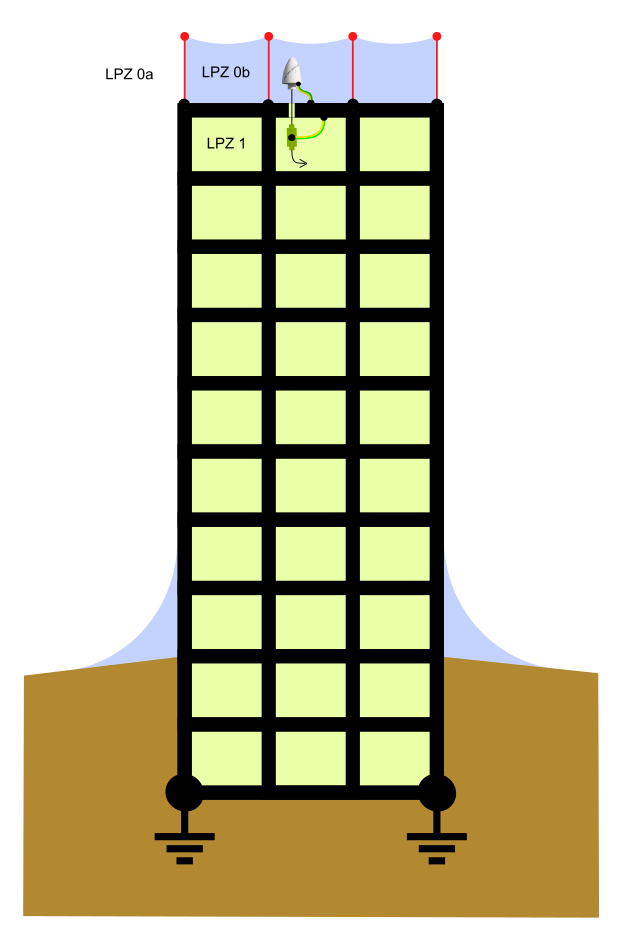
A skyscraper with a thorough steel skeleton
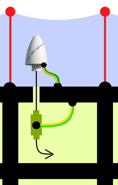
A skyscraper - detail
Q: Can I ground the antenna to the outside LPS?
A: Not to the LPS! Do not ground the antenna to anything
that serves the primary purpose of attracting and conducting lightning.
If you're absolutely sure, that the building has an inherent and massive
natural ground, also serving as a local ad hoc Protective Earth,
it is probably safe to use that - but, avoid connecting to outside
hardware that is specific to the LPS.
If unsure about the grounding and LPS arrangement of the building,
try to keep at least some level of isolation/separation of the antenna
from any existing outdoor metal, which is likely connected to the outside LPS.
Suppose that the classic skyscrapers with a welded or riveted steel skeleton
can easily conduct lightning strikes through that skeleton without breaking a sweat.
I know for a fact, that getting an antenna placed on the rooftop of such buildings
is "difficult to achieve", in terms of getting approval. But suppose that somehow
this is not an issue to you, either.
Suppose the building has suitable "earth terminals" on the rooftop, exposing the
earth of the humungous steel skeleton of the building. That's where I would dare
to earth surge arrestors. I would expect there to be a "building entrance wiring
cabinet for signal cabling", where all the surge arrestors could be co-located
in a rain-proof environment and properly earthed, to a terminal or busbar
prepared for this particular purpose. I've actually seen one such
box on one local highrise.
Try to find out (ask around), how inner PE in any possible "datacenter rooms"
near the rooftop are created. Where is the equipotential bonding point,
relative to the steel skeleton of the building, where the local PE branches off.
This bit of information is key to subsequent conclusions about "safe separation distance"
about the place.
I'd hazard a guess, that it wouldn't make much sense, if your antenna
is on an "antenna mast" a couple (dozen) meters above the roof / top deck,
to bring your very own earth conductor all the way to the antenna.
At the same time, I would not quite dare to ground the antenna to a mast
that also serves as a natural air termination + ownconductor - unless the
cross-section of the mast would be reassuring, and it would be preferably welded
to the building's steel skeleton. Bolted connections, while mechanically robust
enough, may have contact resistance, and these high-up places are very exposed
to direct lightning strikes. An antenna mast this high up is a "lightning magnet".
In general, look around, and do as others do.
Improperly connected gear won't survive very long in such places.
There is one specific scenario, where antenna masts are a plausible ground:
if the mast is "covered" by an isolated air terminator, erected enough above the
end of the mechanical mast, and keeping safe separation, by distance of the bare
parts and possibly by a layer of insulation/dielectric on the down-conductor cable.
Another condition is, that the mast must be grounded to a plausible "inner" PE.
Such as, independently of the LPS, to the massive metal skeleton of the building.
For more inspiration, there's another chapter below,
trying to focus on various problematic scenarios - its very first example
demonstrates this setup, albeit on a small "brick and mortar" house.
By geometric dimensions, a small family home is fairly comparable
to an antenna mast on a highrise (using the building's masive skeleton as a GND reference).
In general, true highrise buildings tend not to have outside lightning downconductors. Even for mundane buildings such as individual family homes, there are dedicated components to build a downconductor hidden behind the surface of the facade. And, there's probably a way to arrange this inconspicuously using structural components of the outer shell of modern highrise buildings clad in glass. In any case, the outer surfaces of a highrise (above rolling sphere radius) have to be protected by "air termination" of some sort, as the space outside the building is LPZ0a.
While synthesizing this skyscraper chapter ouf ot thin air,
I've tried googling a bit (1|2) on the topic.
Which has yielded two somewhat interesting finds:
I haven't found anything about the classic skyscrapers that stand hundreds of meters tall.
But, clearly their builders must have their own idea, how to go about lightning downconductors
and air termination. Any feedback/insight on this would be warmly welcome.
From the perspective of IEC62305: it is possible to use isolated downconducting paths,
using high-volt cables with a thick layer of dielectric. But, making the downconductors
separate from the building, with a bonding node at the base, would only exagerrate the
safe separation problem. Such a downlink's upper terminal above the rooftop would need
dozens of meters of separation, and would not provide cover for the surfaces
of the side walls of the building. Noone has ever built a skyscraper
wearing a sort of a hat with a funeral veil (mesh) around the top.
I've found several sources claiming that buildings above 60 meters of height
(about 20 floors in my small-town circumstances) must have their upper floors
protected against direct sideways strikes, which is perfectly consistent
with the rolling sphere model (maybe even diluting it a bit).
Actually the kc constant in the safe separation formula seems to provide
a "way of reconciliation" of IEC62305 with tall buildings, and what the practitioners
seem to suggest: you need a dense enough mesh protecting the surface of a tall building,
and a good quality natural downconductor mesh in the building's skeleton,
the two of them interlinked. An imperfect step in this direction would be an outside
surface mesh, i.e. with downconductors interlinked by "rings" e.g. at every floor level
(also mentioned by some sources). The system needs to provide surface coverage,
and relatively very low resistance across the enormous height of the building,
and, anti-inductance measures = parallel wiring of downconductors around the perimeter
and inside.
The inductance aspect is important. E.g., a single downconductor at the center of the
building would not be a very good idea, as it would not provide good cover at the perimeter,
and its single path of the pulse current would create a perfect concentration of
magnetic field inside the center of the building, where power and signal cabling
and pipe networks of all sorts are concentrated, including elevator shafts for instance.
A robust mesh, spreading the current, would spread the magnetic field, and would minimize
top-to-bottom resistance. Break down Mr. Kirchhoff and Mr. Henry into a pile of equal
and small finite elements.
Still, interestingly to me, there are numerous sketches on the web,
suggesting a classic setup with multiple downconductors, not even
horizontally interlinked, on a highrise, with a single equipotential
bonding node at the base - yet the resulting problem with safe
separation is not mentioned.
To me, this is another proof that the IEC/EN 62305 can be a pain in many
different scenarios, where it deprecates legacy practices :-)
Where I live, just as I'm typing this text, I have a view out of my window, of some rooftops on neighboring buildings:
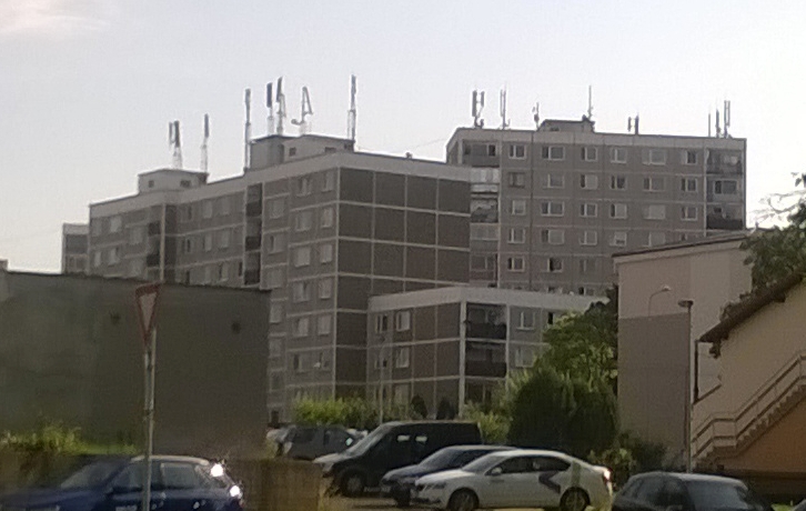
Note how the LTE "antennas" (outdoor units) are mounted on additional masts.
As far as I can tell, only on the tallest building, the masts have an extra
"air termination extension" - a piece of rod, directly attached to the mast,
the rod reaching about 1 m above the upper end of the antenna "cigars".
The LPS air termination and downconductors are unlikely
of the isolated/distanced persuasion.
I am told that 4G (LTE) outdoor units use fiber optic for their data link
to the base station. Thus, the outdoor unit only needs metallic cabling
for power supply, which is relatively easy to protect by arrestors.
I haven't been on those rooftops, I don't know details, all I know is that
this particular block of buildings, the tallest in the neighborhood,
regularly score a hit during every self-respecting thunderstorm passing across
our city.
I've tried to find something about the legacy/original reference solution of LPS on these buildings. There have been several generations during maybe 2 decades... Google finds mostly complaints from people who need to address the LPS during a reconstruction, or when adding something on the roof, only to find that the legacy LPS is either not certifiable to IEC/EN 62305, or just plain broken / defunct even by the previous standards, and difficult to revamp to pass contemporary inspection.
On the outside, I can see that some of buildings of this type
are missing external downconductors. I've found notes that
"natural" downconductor construction is an option (using rebar,
elevator shaft rails and whatnot), that this type of LPS design
can be used during a reconstruction (it is one way to satisfy the EN62305),
that it may require vertical pipelines in their shafts deep inside
the buildings to be refurbed to make them nominally capable of conducting
lightning currents...
Either that, or the building may have just one or two legacy external
downconductors that I have missed while casually walking around.
As for rebar, these commie-era buildings were assembled
on site out of flat prefabricated panels of reinforced concrete,
and the panels had rebar eyes for crane hooks and specific
"rebar-attached steel interfaces" for welding the panels together on site.
I don't have further details, but chances are, that the
"faraday cage of rebar" can indeed turn out to be half decent.
And then I've found a reference project in PDF, from a local branch office of Dehn, for this general type of panel buildings. The Dehn design proposes using HV-isolated downconductors around the perimeter, obviously to reduce the "safe separation distance" required - and air termination is only constructed above the roof, safely separated by plastic (fiberglass?) vertical spacers. My impression: this way of tackling the "safe separation distance" on the perimeter walls is obviously also correct, and permitted by the fact, that these buildings normally didn't exceed 40-45 m of height, so that sideways air termination (protection of perimeter walls) is not required.
This scenario is very real, but in terms of practical experience,
once again I'm fabulating. I can give examples of such buildings/structures,
but I cannot claim practical experience. I've never visited the upper
decks of any such tower - because I'm not in that business,
and also because my self-preservation instinct would strictly prevent me :-)
Thus, all I have is a limited amount of word of mouth, from existing customers.
And, I have the IEC62305.
The key assumption of the sketches in this chapter is,
that the whole tower is a steel "monolith".
In reality, this is often true about smaller towers,
and even these will likely be bolted together from smaller sections.
The largest transmitter towers tend to have a bottom part of the tube
made of reinforced concrete, followed by a steel tube extension,
possibly with a plastic radome forming the top section.
Whatever the details of the construction, this is the sort of a building where grounds are in good shape, the steel tube section is an ideal natural down-conductor for the LPS, and techie people taking care of the place likely know where the surge arrestors are to be placed (I am told the place may be ugly / difficult to access).
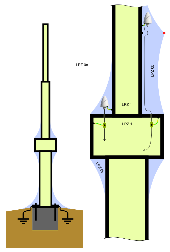
A tower of steel
Q: Can I ground the antenna to the outside LPS?
A: Not to the LPS! Do not ground the antenna to anything
that serves the primary purpose of attracting and conducting lightning,
even if it's "equipotentially bonded" a few meters away to the massive steel body.
It is relatively likely, that any massive steel construction in a radio tower
will be well grounded, and used to branch off a local PE where needed.
While you probably won't be allowed to weld your own nut/terminal
to the steel body of the tower at any point of your choice,
probably, around antenna masts / mounting places, protective earth
terminals should be available, or the local mast itself
will be covered against a direct strike by "dedicated air termination".
Depending on how well the tower is managed anyway.
Typically, antennas tend to sprawl at such places during the years,
and the exponential grassroots growth may pose "challenges" to site management...
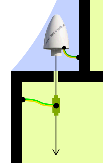
A tower - detail 1
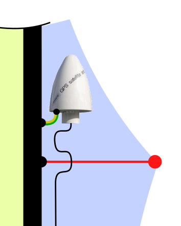
A tower - detail 2
I've promised some word of mouth... an old practitioner has mentioned to me, decades ago, that at such locations (towers), a single coaxial arrestor was not enough. Two of them in a cascade were allright. One "at the top" near the antenna, another one "at the bottom" = at the boundary/entrance from LPZ0 to LPZ1. Both arrestors were the direct-earthed variety. Where did he ground the upper arrestor? That's probably anyone's guess... but it would be a good spot to ground the antenna, if it has the option.
The Dehn Bible actually has a chapter on lightning protection of LTE base stations, starting on page 355, with a nice full-page picture of a mast on page 358.
To close the chapter on a light note, let me add a few photoes of some existing large TV transmitter towers in the region.
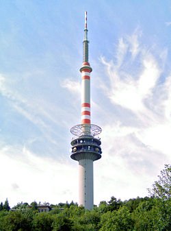
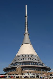
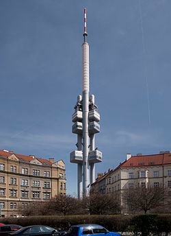
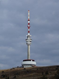
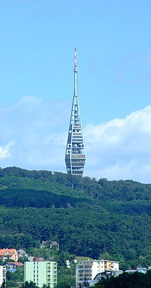

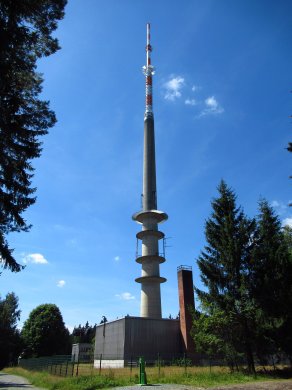
All the photoes come from Wikipedia - they're clickable and that's where
the links point to.
I haven't tried to make the collection of photoes more diverse, yet I'm sure that the spectrum of sizes, shapes and constructions of radio towers is probably vast.
And again I will be fabulating. Being a citizen of a landlocked country, I have to think hard to remember the times when I boarded a boat, let alone a ship... possibly a ferry from Rostock to Trelleborg would count?
In this chapter, I will suppose that serious ships of different classes
and purposes, ultimately, feature a body welded together out of sheet steel.
Everything from the hull up, through the upper decks, the bridge / wheelroom,
perhaps including the radar mast (?), can be relied on to be massive
and firmly welded together.
Based on that, I further presume that a solid ground is available
"virtually anywhere" - even if you don't dare to ask permission to
weld your own PE terminal to her body anywhere you like, you will likely
find suitable existing PE terminals or PE busbars at places where they tend to be needed.
If that's the case on the radar mast, than that's the case. I have no clue.
The fact that the seawater under your hull is the best possible "earth" you can ask for, that's just a cherry on top of the pie, and not very relevant TBH.
So starting from that overall "architecture", I dare suggest the following approach:
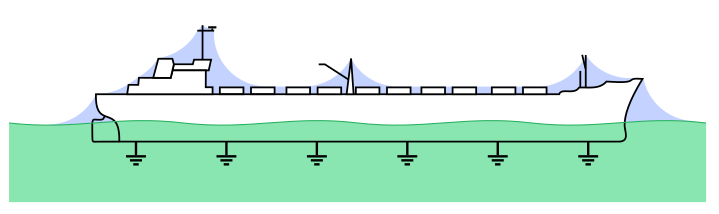
A ship - from a distance
So much for an overview picture.
Our antenna is comparatively so small, that it doesn't seem fruitful to me,
to attempt a simplified sketch at this resolution.
Let's zoom in on the upper decks and the bridge:
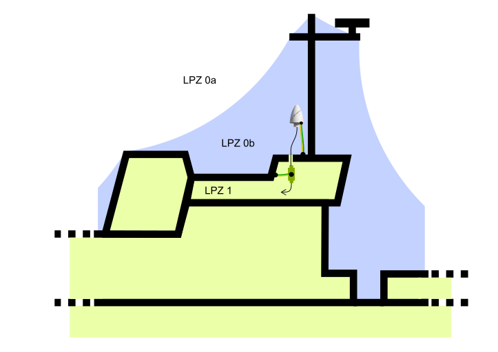
A ship - the bridge up close
As you can see, my sketch is still heavily "schematicized" - I don't intend
to reconstruct a realistic section through the interior of a bridge
or "Computer/DC deck" or whatever its name actually is.
I will zoom in one more time, for those of us whose eyesight is no longer
razor sharp (mine is definitely not). I hope you get the idea...
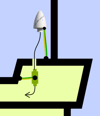
A ship - detail
Q: Can I ground the antenna to the outside LPS?
A: Not to the LPS! Do not ground the antenna to anything
that serves the primary purpose of attracting and conducting lightning,
even if it's "equipotentially bonded" a few meters away to the massive steel body.
Other than that, if the "massive body of welded steel" is true, you can probably
ground your arrestors and your antenna pretty much anywhere suitable.
Anywhere where you don't inherit some contact resistances shared with
the path of the potential lightning current.
No photoes in this chapter - no suitable objects in my area :-)
I'm wondering if there are any marine electricity/safety norms that would have a say in this scenario. Talkback welcome.
The Dehn Bible actually has a chapter on lightning protection on Yachts, starting on page 452.
Now this is a scenario that I am marginally familiar with.
The sort of outdoor substations, built and operated by the energy facilities
in our country,
tend to have small brick-and-mortar buildings scattered throughout the site,
intermixed with a forest of pylons and some other support structures,
various outdoor high-volt sensor and actuator devices etc.
In a distribution substation, you would likely find a transformer or two.
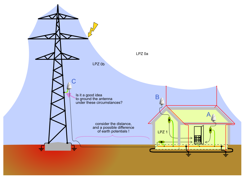
The sketch below depicts three potential positions, where to place antennas,
labeled A, B and C. In my experience, I've only ever seen A or B.
Placement "A" is good enough for undemanding applications (NTP and the like).
Still the antenna should at least see above the rain gutters, to see
a wider angle of the sky above the sloping roof.
If there's no better option, placement "A" works half decent even for
high-performance timing (PTP and other tech at that level), where
placement "B" is generally more appropriate - again with an optimal
view of the sky as an optimization criterion.
Placement "C" is with a question mark. How real vs. silly this is, that depends
a lot on the particular arrangement of the buildings, pylons, power electric gear
etc. about the facility. In the configuration that I've sketched above,
and deliberately exagerrated the troublesome points a wee bit to make them clear,
placement "C" does not seem very fruitful or safe. Your customer may call
it "out of the question" for very particular reasons (norms for substation
design and safety). In a substation, the 400+ kV lines can be just a few meters
above ground, safe distances are squeezed as close as realistically possible...
Q: So: can I ground the antenna to the outside LPS?
There is one particular aspect, where my sketch above is admittedly
unfair / not entirely correct: I have depicted the pylon and the building
as each having its own earth termination.
An orthogonal grid made of steel bars, each bar several hundred mm2
cross section. Across the substation site, the grid varies in density, to satisfy
several design criteria. There's a minimum density, and additional links get added
around power devices, pylons etc. Around each house (brick and mortar or otherwise),
there's a dedicated "ring", in addition to the background spacing of the basic grid.
A house needs to be connected to the earth grid by at least two links.
The same apparently applies to pylons and smaller support structures.
Transformers need to be earthed by four links to the earth grid.
Also note the additional ring just outside the perimeter fence.
The primary purpose of this grounding setup is not lightning protection.
The point here is, operational stability and safety of the substation
under load and during failure events.
Another obvious and desired effect of the earth grid is: minimized
resistance against "background earth". Obviously the net result
also depends on soil resistivity and the underlying geology.
Lowered resistance to background earth translates into a lowered
voltage difference and gradient upon a HV failure or a lightning strike.
Yet, reportedly, the residual gradient is still harmful to any
fauna living in the soil in or around the substation (rodents, worms etc).
All transmission and distribution substations have this uniform
earth grid. Only railway traction power substations are a notable exception:
reportedly, the railway traction side earth must be separate from the
"mains" substation side earth grid.
This is to avoid the railway return current from mixing with the mains earth.
Probably a factor especially in DC traction, where you want to avoid
a "DC bias" in the huge AC transformers.
Reportedly, any group of buildings and structures that comprises
an industrial plant or facility, should also have interconnected earth.
Not just in the electric energy business - any sort of industry.
Arguably, something like a warehouse district with no substantial machinery
won't need as much focus on grounding as... say... a heavy industry
area hosting a century worth of coke production, iron smelting,
steel metallurgy and rolling, stamping and welding...
Does the presence of an outdoor earth grid make any difference
as to antenna placement and grounding, as suggested in the
"substation sketch" at the top of this chapter?
In this chapter, I would like to debate scenaria that are "compromised",
and your options how to approach them.
In realistic cases, where you need to place an antenna on someone's rooftop,
you will sometimes (rarely/often?) get into situations where the building either doesn't
have an LPS, or has one that used to be mostly allright under past LPS norms,
but won't make it through a current IEC-62305 inspection. And you just need to place
your little antenna - but the building including your antenna won't be compliant
with IEC62305 and you're the last one to put stuff up there on the roof.
If a lightning strikes, and "something happens", guess who will attract all blame.
A proper IEC 62305 LPS can be expensive. A certified LPS has always been expensive,
and as soon as e.g. isolated downconductors get in the picture,
or isolated air termination on certified fiberglass spacers, that's where it
starts to hurt. And, earth termination is not a piece of cake either.
If your existing earth termination is no longer worth a dime, or non-existent,
to build a proper new one you may need to dig a trench around the house...
oh your house is squeezed in a row in some downtown street, with a pavement
along the front, with a number of networks already buried?
You need approval for digging, including contributing approvals from all the
network operators in town? Hard cheese...
Don't despair, all hope is not lost, as long as you can get at least
the earth termination sorted = use an existing one, or implement a minimal
new earth termination setup. The Dehn Bible on page 292
mentions a few versions of a minimum earth termination, including dimensions
If you ever face a building, that has no LPS and no proper earth termination,
and there's no chance of making some proper earth termination of your own,
your best option unfortunately is: retreat. Run away. Not worth the responsibility.
Apparently there are a number of people, e.g. among WISP's, who just don't care.
Install the outdoor unit, plug in the CAT5e carrying data + PoE, and run.
If this is on a roof, the WISP has probably just clamped the ODU to the only existing
antenna mast up there, that also doubles as the tallest air termination of the outside LPS.
After all, this is how it's been working for decades.
I am deliberately abstracting from scenaria, where you just tuck your antenna
outside a window in a deep LPZ0b, maybe ground an indoor arrestor to the PE in a wall socket
and go home. That will hopefully work for many applications
(in Meinberg parlance, it might as well get NTP started, eventually),
and won't require installing cables across several floors in an existing building.
On to some modest/basic examples:
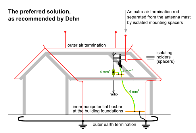
This solution is based on the optimal scenario, where the building has an existing LPS.
This setup is promoted by Dehn - see the Dehn Catalogue on page 19,
and also the Dehn Bible on page 294,
the two pictures at the bottom. It scales to any sort and size of a building, limited only
by the density of LPS-connected metal objects on the roof. It presumes that you can find
a place, where safe separation of your mast and antenna is achievable.
If you actually do have an existing niche of LPZ0b, where you can place your own mast,
safely separated from the LPS - that's an even easier situation:
you don't even need to add an additional air termination rod.
Before I get to the point, please note, where the added antenna mast is earthed.
That's right: to the inner PE of the buiding. And the conductor doesn't even
have to be very thick.
Q: So: can I ground the antenna to the outside LPS?
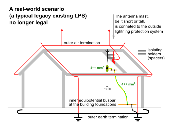
Again let's have a building with an existing LPS.
The older version of the lightning norms (national, where I live) did not make so much
fuss about safe separation. LPZ's did exist, but anything on the roof that was made of metal,
had to be strictly linked to the outside LPS. Including antenna masts - which often doubled
as lightning rods (or a handy base for the rod itself). Separated LPS mounted on isolating
spacers just didn't exist.
Suppose that there's no way to add another antenna mast, albeit modest,
and the antenna installer is referred to an existing mast, which is a part of the LPS.
In such a scenario, perhaps the only legal way out is:
do not place an antenna on that roof, period. Retreat, give up.
Or, while I don't want to advocate for this, or hope for impunity,
technically you may want to "do as much as technically possible"
(and take the legal risk).
Obviously you won't find this picture in Dehn documentation :-)
Make sure that the LPS earth termination and downlinks and equipotential
bonding are otherwise in good order (without a good earth at the bottom,
I would refuse to do anything).
Try to mount the antenna such that it is isolated from the outside LPS,
including from the antenna mast available.
You probably won't be able to achieve the level of safe separation
calculated as per IEC 62305, but imperfect separation is still
better than no separation at all.
I have debated about this with some inspection engineers...
off the record, they'd nod their head approvingly.
That the practical measures outlined above, while they won't
clear the system to achieve IEC62305 approval
(compliance with the norm is all or nothing),
in actual fact do go a long way to minimize harm,
coming from the antenna downlink, should a lightning actually strike.
If that is some consolation, note how thin coax cables tend to be.
Compare the cross-section of copper in the coax cable,
to the cross-section (resistivity) of LPS downlinks,
or a 16mm2 internal PE. A longish side-channel arc
in ionized gas won't beat a solid ground either.
Meinberg angle: To sum up, let's not forget our fundamental question for this particular scenario:
And remember: this whole chapter is illegal.
In this example, the antenna installation team faces a building with no outside LPS.
A possible solution is, to install a single, isolated, "air termination rod",
mechanically supported by the newly added antenna mast. And, run a proper outside
LPS downlink, to a proper earth.
The Dehn Bible seems to suggest this on page 295 (the picture on the right).
The original picture features an HV-insulated downconductor (a product of Dehn).
Effectively, the building gets a minimalistic and possibly deficient LPS,
where originally it had none.
Note: the system needs an earth! If no existing earth termination is available,
one needs to be constructed as part of the project.
For inspiration, feel free to check the Dehn Bible on page 292.
As for our fundamental question, for this scenario:
In this example, the antenna installation team faces a building with no outside LPS.
And the suggested solution is, to run a 16mm2 copper cable along the
outer surface of the building, perhaps hidden under the roof tiles in that section of the route.
This setup comes from the Dehn Bible, page 295 (the picture on the left),
repeated in a slightly different form in the Dehn Catalog on page 19,
the bottom left picture.
Note: the system needs an earth! If no existing earth termination is available,
one needs to be constructed as part of the project.
For inspiration, feel free to check the Dehn Bible on page 292.
As for our fundamental question, for this scenario:
This is merely a relatively small variation of the previous solution #2.
In this example, the antenna installation team faces a building with no outside LPS.
And the suggested solution is, to run an inner Protective Earth, worth 16 mm2 of copper,
inside the building. The route should be straight, with no loops or even unnecessary meanders and bends.
This setup comes from the Dehn Catalog on page 19,
the bottom right picture.
Note: the system needs an earth! If no existing earth termination is available,
one needs to be constructed as part of the project.
For inspiration, feel free to check the Dehn Bible on page 292.
As for our fundamental question, for this scenario:
In this chapter, I'd like to skim just very briefly the topic of surge arrestors.
For my (Meinberg) practical purposes, there are two noteworthy variants of the arrestors:
The following picture shows the possible inner schematics of some example arrestors that I have met,
and their cascaded placement in the antenna downlink signal chain.
Using two arrestors in a cascade improves protection = safety.
Let's take a look at the signal chain in a little bit more detail:
The issue of ground loops doesn't seem very painful.
If in doubt, it's nice to try the second arrestor direct earthed vs. isolated,
compare RX quality figures, see if there's a difference... Don't expect to find much.
In general:
for the 1.6 GHz band (and 1.2 as well), the wavelength is about 185 / 250 mm
in vacuum, times 66%-85% in a coax cable. At high multiples of the wavelength,
do not expect a loop to work as an efficient antenna. Also the attenuation of the
useful signal is such, that any impedance mismatch effects (reflections, impedance
transformation) won't work around loops spanning many dozen meters.
Thus, at these high bands, the ground loop effects are unlikely to present a problem.
Just use two direct-earthed arrestors in a cascade, if you need to, for safety reasons.
This is also convenient in combination with receivers that don't have galvanically isolated input.
Speaking of the Meinberg 35 MHz band (35/10 MHz actually), that's where the length of antenna
downlinks might play quarter-wave tricks with an external ground loop. This is also where
the earth-isolated arrestors have some merit, given their often more limited
bandwidth. If unsure, in the context of a particular trouble case (poor RX quality),
feel free to try different arrestor setups. Don't expect to find too much of a difference.
It makes no sense to use and earth-isolated arrestor just before an antenna
input on a radio that does not have input isolation = where coax shield
is connected to chassis ground. If some energy comes down the antenna downlink's coax
shield, it ends up finding its way through the radio, instead of
getting guided safely away by a prepended arrestor.
Still, no matter how tightly you manage to protect the input,
it is nearly impossible to protect against in-band RF energy.
The arcing of a lightning strike produces lots of broadband RF AC noise (power),
some of it in the band passed by isolators and even passband
filters... this is nearly impossible to limit, without
preventing reception or demodulation of the desired useful signal.
Some vendors produce "combined" arrestors with multiple stages in one package, for various types of signal.
Unfortunately, protection factor with the finer arrestors often contradicts bandwidth.
I'd like to call this chapter "theoretical".
It may surprise you or it may not:
the behavior of electric field in insulators (air) and in conductive materials (earth)
has quite a bit in common, at the bottom line.
Let me start this lecture from a scenario, that does not apply very much to our overall topic (lightning).
Things get more interesting, as soon as you consider "point charges" and spherical electrodes.
The first issue is: fine, so one of the electrodes is now just a dimensionless
point, or a smallish spherical object. What about the other electrode, what does that one
look like?
Where I'm going with this:
Note that around the smaller ("point") electrodes on the left,
the gradient slope reaches relatively higher,
than around the larger electrodes on the right.
This is an important implication of the math detailed below.
The field "concentrates" around the point charge / small sphere.
Around a point or spherical charge, the scale of potential (Voltage)
actually becomes hyperbolic: 1/r (times a constant).
Where "r" is a radius, a spherical coordinate, starting from 0,
but practically bounded by the outer spherical surface of the electrode.
In a spherical electrode with a non-zero radius of its own,
the hyperbolic curve "virtually" starts descending
from the ideal center, but only actually materializes
starting from the surface of the electrode (outward).
Thus, other conditions equal (the same Q = charge),
a larger spherical electrode produces a lower surface Voltage.
But the rest of the hyperbolic curve = potential fading out into 3D space is the same.
Which also means that the E = field intensity = gradient, slope of voltage
(ΔV/Δr), starts at a lower value, around a larger object.
I may later try to infer some reasons for the hyperbolic curve, but for the moment, let me focus on some interesting consequences:
Paradoxes of infinities aside, the effect of the field concentrating
around small charged objects has interesting practical consequences.
In the air, inevitably, at a certain non-zero distance from a sharp spike,
the gradient (ΔU/Δs [V/m]) trying to converge to infinity
locally exceeds the isolation capability of air, and produces localized
breakdown / silent discharge. If the charge is large enough / fed by a power supply,
the silent discharge may grow into a visible and audible corona,
and possibly further into an arc, if there is a suitable opposite
electrode near by.
This is one partial reason why Van de Graaf generators typically use a prominent
sphere as the upper electrode collecting charge. Add a little spike on top,
e.g. made of a paper clip, and the generator won't be able to keep its charge
for very long. Same thing with a "Leyden jar" - do not leave open-ended
wire attached to its terminal, if you want to keep it charged.
If you try to discharge the ball on top of a Van de Graaf generator,
e.g. using a piece of grounded wire, preferably terminated by a metal ball,
you'll likely provoke a loud snappy spark. But if you add a spike on top of
the Van de Graaf's upper sphere, chances are that the generator
will lose charge relatively silently and gradually, especially as you bring
your grounded discharger gradually closer to the spike.
You may hear a faint hiss while carrying out this exercise.
The more energetic experimenters may prefer Tesla transformers.
For maximum show, these devices tend to feature spiky electrodes,
giving mighty visible coronas... or long jagged sparks.
This is also why lightning collector rods ("air termination" in modern newspeak)
often have a sharp tip. This turns them into nature-favoured candidates for a grounding
point for any lightning looking for a spot to hit. The precise mechanism is,
that as the overall gradient from the sky intensifies (while the downward leader
is getting closer), the tallest and spikiest objects attached to ground are the first
to surround themselves with the sort of gradient to break the air's isolation
strength, and therefore have the best chance of starting a corona, eventually overgrowing into
an ionized upward-growing "welcome channel", which effectively extends
the spike-tipped air termination rod further up.
In the earth, the principle of operation is "ohmic", but the curves turn out to follow similar principles.
The earth resistivity depends a lot on geology: presence of moisture or standing water, dissolved salts.
Solid rock such as granite can have several decimal orders higher resistivity than moist clay
or water-soaked sand.
An underground water table near the surface can be a boon for grounding,
but beware of building your substation on an underground asphalt lake for instance :-)
And yes, geology tends to be layered. So much for our idealized spherical math.
A deficient earth electrode, when hit by a lightning, will likely produce an ionized
space in the earth material, which will inherently decrease nominal resistivity... but that's
not too much of an excuse or consolation, as relying on that effect basically implies
that the residual voltage on your LPS will be "impractical".
Again the norm goes a long way to specify how air termination, down-conductors and
earth termination should be dimensioned, depending on geographical location / latitude,
geology, and various other circumstances. Construction details, such as various sizing
and spacing rules, for specific industries (such as energy transmission and distribution)
tend to be further specified by internal/proprietary norms of the respective facility companies.
Let's close this chapter by a bit of actual math.
In the four formulas below, the radius is our independent variable,
and the rest of the letters on the right side are constants.
Among them, all the four formulas contain the inevitable π ,
as we're dealing with spherical concepts
(equipotential surfaces in 3D).
The theory of static field typically starts from the hyperbolic curve of potential distribution,
in a spherical arrangement around a point charge.
Specific constants in this formula:
The field intensity, AKA gradient, is a local slope of the "potential" curve, i.e. its first derivative:
On to the next formula, and to conductive medium.
In a conductive material, the slope of things is pulled by a given current,
and the resulting "concentric map of voltage levels" emerges out of a series
of partial resistances, over infinitesimally small sections of "r"
(the spherical radius). Therefore, it's probably easiest to start
mathematiculating from the resistance. Around a spherical electrode,
the conductive material in the surrounding space forms a conductor
with a gradually growing cross-section. The cross-section is a spherical
surface with a radius of "r". If you multiply that cross-section (along "r")
by material resistivity (ρ) and by the given current,
you end up with a local ∂V/ ∂r , i.e. you get directly
the field intensity.
Specific constants in this formula:
The cumulative Votage or Potential curve is then easily obtained
as an integral of the previously determined intensity.
For "r" converging to infinity, the Voltage asymptotically converges
to 0V, which sounds like a good choice of constant for a background earth potential...
And please don't nitpick about the sign (+/-) on the intensity.
Apart from a direct hit, a lightning can mess with nearby wiring indirectly: by way of inductive coupling.
Even if the building in question has a duly designed and constructed outside LPS, and a properly wired tree of
PE on the inside, despite all proper isolation and separation, even then:
In other words, imagine that the lightning downconductor, and your signal cable in the building, comprise a primitive transformer.
Turns out, that the inductive "transformer effect" can in fact be surprisingly significant.
What does matter a lot is the frequency range, or ΔI / Δ t .
The math that can be used to describe and understand these phenomena turns out to be surprisingly simple and straightforward,
combatible using high-school level knowledge.
Essentially, even a section of straight wire has inductance. It may be difficult to independently measure,
as by attaching probe wires, you form a loop - but it's probably safe to believe the wise men who have coined
the formulas for us...
Let's get to the first formula. Let's start with coupling between two parallel
straight wires (AKA filaments, in the source literature).
The wires in the formula are considered ideally thin = wire diameter is not reflected.
μ0 is the permitivity of vacuum (air has almost the same) = constant, the π is a constant too.
The point so far should probably be, that a large ratio of l/d results in a high mutual inductance.
Yeah right... inductance between two coils... where are we going with this?
So the next step is, that the mutual inductance plugs into a formula
for a so-called "coupling coefficient" between two inductors:
And if the two inductors are the same, we get:
The coupling coefficient k is a unitless ratio on a scale of 0 < k < 1.
And indeed it seems to translate approximately, into how much voltage (or current?)
you get on the output of a non-ideal transformer, with a transformation ratio of 1:1 (turns ratio).
Except I've never seen its purpose defined that way - we'll get back to that.
Oh wait... where do we get the own inductance L of a single straight wire?
The two input variables are:
In practical terms, 1 meter of a wire can have roughly 15-20 microHenry
of own inductance (depending on how thick) and two such wires spaced 10 cm apart
will have about 8 microHenry of mutual inductance.
Here you are an Excel table for some "back of an envelope" calculations...
50 per cent... sounds spooky or what? Where does frequency or slew rate come in the game? How do we get to some voltages, finally?
I've ended up simulating the behavior of a lightning down-conductor in Qucs Studio,
using its "file-based current source" element.
To us near the ground, lightning behaves a lot like a current source. Typically not a constant current, but given.
The difference of potentials between GND and "somewhere up in the clouds" can be a couple hundred million Volts.
Once the arc strikes, having found a path through a couple hundred meters of air, that it had to ionize first,
resistances in the LPS in the units of Ohms (or thereabouts) don't make a difference to the current flowing
our way from the accumulated charge up above, possibly draining additional nearby clouds of charge available up there.
Our earthly resistive and inductive effects therefore transpose directly into voltage values.
After an initial tuning of the simulation setup and seeing the first results,
I've sketched the following explanation of what's actually going on, as some of the details
are not obvious from the QucsStudio output (e.g. the current waveform is not in the raw sim charts).
The raw content of the input CSV file (current waveform) looks like this:A substation
During the years, on and off, I've been in touch with several
customers in this business, hopefully I learned a bit about
the environment and the issues that they need to address,
which I should not speak about in great detail...
Preferred antenna placement is something solved for good, we actually had some
fine-tuning to work out.
Control hardware tends to be located inside the brick-and-mortar buildings,
sometimes rarely in an outdoor "wiring cabinet" e.g. next to a free-standing
transformer.
Variant C has been suggested by someone at a Meinberg meeting, and I actually
had something similar in my own older materials, only with a free-standing
transformer, possibly not very real... therefore, variant C is included here
for completeness, even if as "food for thought" and "subject to further debate".
Some of which follows within this chapter.
A substation
In a different scenario, the overall merit may possibly lean
in favour of variant "C"... it really depends.
A: Not to the LPS! Do not ground the antenna to anything
that serves the primary purpose of attracting and conducting lightning.
Long story short, the internal PE is your earth of choice for
surge arrestors and theoretically also for outside holders
and antenna, all in LPZ0b, if distant enough from the outside LPS.
The building in my sketch (and in my reality) is "brick and mortar",
typically having just a ground floor and an attic under the sloping roof.
At that modest height, "safe separation distance" is not extremely painful,
so you probably won't see insulating spacers or some such
high end measures as part of the outside LPS. The building is a low-end case
of the brick and mortar example above.
I also have some troubled cases in a chapter below,
relevant to this scenario.
In actual reality, this is just not true. As a rule, substations of any kind
have an underground "earth grid" spreading allover the place:
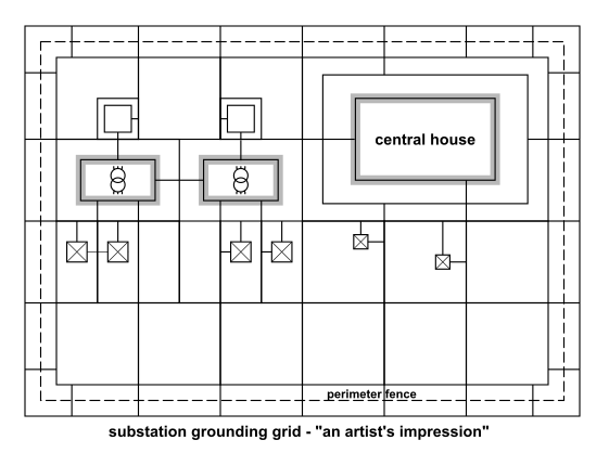
An on-premises substation grounding grid
The picture is actually fake, sketched by me, resembling an actual design.
For real-world examples, try Google images.
In our reality, the 440kV AC high-volt lines normally carry some kiloAmps
continuous AC current. During failure events, the fault current can be
in the tens of kiloAmps. This is what the substation is designed to handle
non-destructively = disconnect such current when a failure is detected.
The earth grid is dimensioned to take the fault current without melting.
Even in a correctly designed earth grid, buried in the earth, the bars
forming "path of least resistance" of an accidental fault current
can heat up to a couple hundred °C within seconds of the failure's
duration. After that, the protection relays should trip and disconnect
the overloaded direction.
Another role of the earth grid is to reduce step (stride) voltage during
a failure event, so that human personnel at the substation doesn't get hurt.
I suppose it doesn't. Doesn't make "variant C" any more appealing.
Voltage gradients occuring upon a lightning strike or HV failure
do indeed get diminished, but unfortunately not eradicated completely.
Also, loop area matters - will be debated below.
If possible, avoid making the coax downlinks too long outside the building,
especially in this particular environment.
After all, the people managing the site will probably have an opinion.
Troublesome examples - reality bites
This chapter probably isn't very relevant to Meinberg customer cases.
But if I want to make this howto "more open" and cater for other walks of life,
I feel compelled to address this topic here.
Effectively, this chapter ventures further along the lines of grounding and safe separation.
You may find yourself pressured to give up safe separation,
or you may even find your antenna and downlink to be the undoubted #1 path of least
resistance to ground, on the whole roof. Regardless of whether you just want
to help a friend, or you're trying to serve a customer, you may easily find yourself
in a silly "blame game". Along the lines of
Building owner: "So... you'd like to install an antenna on my roof?
then be so kind and accept the blame, if my so far unprotected house gets hit
by a lightning. Oh you want me to build a proper LPS first? Nah...
first of all I cannot be bothered, secondly - isn't that covered by that
price proposal for antenna installation?" etc.
From there, in the minimal variant, you can cater for your modest
antenna mast added on the roof and be somehow done with it.
Read on for details.
For such cases, you don't need to read this howto.
The one proper way
The premise of this example is, that you can add your own minimal mast,
the mast can be mounted safely separated from the existing LPS,
and if the existing LPS doesn't provide a suitable niche inside LPZ0b
(i.e. so far we're speaking LPZ0a), such a niche of LPZ0b can be created
by attaching an isolated air termination rod to our minimal antenna mast.
This can be done in two ways:
a) using isolating holders/spacers
b) using a section of an HV-insulated lightning down-conductor. (Available from Dehn...)
Antenna mast added, with isolated LPS air termination
Just to make sure that this point sinks in: as per IEC 62305, you can have metal parts
on the roof, that are not linked to the outside LPS. Even more perplexingly, they may be
(should be?) earthed to the inner PE of the building. Provided that they are located
in a LPZ0b, created by an overhead isolated outside LPS, and that safe separation
is maintained.
A: Not to the LPS!
Q: Allright: can I ground the antenna to my added antenna mast?
A: Yes you can :-) Considering where the mast is grounded...
So the antenna holder need not in fact be isolating.
Apply your own taste to the issue of a potential ground loop,
which can theoretically affect signal transmission in the antenna downlink.
An alternative, old, improper way
Except in this example scenario, suppose that having the outside LPS isolated
from the antenna mast is a problem for some reason.
Or, suppose that the roof is covered by sheet metal, which is principally connected
to the outside LPS - in the traditional fashion of previous LP norms.
Therefore, you have no physical possibility of achieving safe separation
of a newly added antenna mast from the outside LPS.
And, you're required to "just do your job".
Note that this train of thought is my own, in no way endorsed by
Dehn or anyone else in official authority.
Antenna mast added, connected to outside LPS
Try to achieve isolation wherever possible.
For instance, if you need to pass through a metal roof, use an oversize
plastic cable gland plus a plastic pipe around the cable.
Inside LPZ1, pay extra attention to surge protection measures
on the signal downlink.
Two arrestors cascaded is a good idea, and if 4 mm2
is the typical requirement for the PE leash with this class of surge arrestors,
don't be shy to bring the inner PE up to your arrestors using
a thicker conductor. As a particular wire gauge, I'd like to
mention that 16 mm2 appears to be the minimum value
when grounding individual antenna holders in LPZ0a (see also
the following chapters) so it could be a relatively safe bet
in this "abominable" scenario, for inner surge arrestors.
After arrestors, if your "radio" does not have an internal
galvanic isolation on the signal input, add your own externally,
if technically possible. A couple hundred Volts of isolation
capability is enough, after the arrestors. Alas, as a side effect,
passive signal isolation breaks DC phantom power to the antenna,
if such is present - which can be worked around etc.
Also note that, in direct-earthed coax surge arrestors,
those made of massive metal, the outer shell probably
survives much more, than the actual arrestor component
inside (a gas discharge tube) that protects the central
signal wire, and the shell is also a more direct path to earth.
Mr Kirchhoff is there to help you, if you help him.
You should take care to make your grounds solid.
1) mind the beautiful, large, plastic antenna holder,
shipping as a standard accessory of the AW02,
the GPSANT and the GNMANT
2) the GPS and GNS-UC radioes have input isolation (unfortunately not the DCF77 nor GNS nor GNM)
3) suitable coax surge arrestors are in the price list
4) the antenna signal can also be carried over optical fiber.
Meinberg hardware goes a long way.
Q: So: can I ground the antenna to the outside LPS?
A: Not to the LPS!
Q: Allright: can I ground the antenna to the antenna mast?
A: No! That's connected to the LPS!
Building with no LPS, solution #1
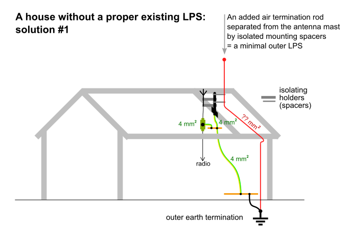
No LPS, solution 1
My emphasis: it would likely work with standard (non-isolated) outside LPS downconductor,
and a physically separated air termination rod on plastic spacers.
My emphasis: the picture from Dehn does not mention downconductor cross section.
I'd suggest a minimum of 16 mm2 copper or about 50 mm2 galvanized steel,
as these tend to be the absolute minima for outside LPS downconductors, as per IEC 62305.
Q: So: can I ground the antenna to the outside LPS?
A: To the minimal separated segment? No! Not to the outside parts, dedicated to conducting lightning.
Q: Allright: can I ground the antenna to the antenna mast?
A: Yes you can :-) The antenna holder actually needn't be isolated. Maybe give some casual thought to potential ground loops.
Building with no LPS, solution #2
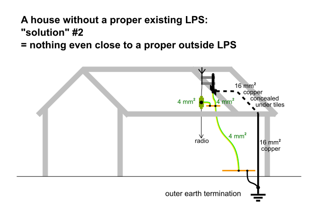
No LPS, solution 2
Note how the earth system is no longer painted as an LPS in the Dehn docs.
Probably because its parameters and "profile" are too deficient.
Q: So: can I ground the antenna to the antenna mast?
A: Yes you can :-) The antenna holder actually needn't be isolated.
Maybe give some casual thought to potential ground loops.
Building with no LPS, solution #3
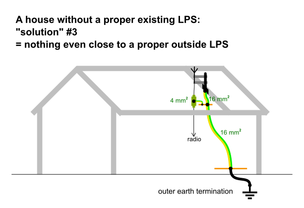
No LPS, solution #3
Note how the earth system is no longer painted as an LPS in the Dehn docs.
Probably because its parameters and "profile" are too deficient.
Q: So: can I ground the antenna to the antenna mast?
A: Yes you can :-) The antenna holder actually needn't be isolated.
Maybe give some casual thought to potential ground loops.
More complex cascaded protection of a signal line
There's a specific product category of arrestors designed for coaxial transmission lines.
By mechanical form factor, they are made to be compatible with popular types of coax connectors.
Different models vary by bandwidth and level of protection...
Putting on my Meinberg hat, I only have use for broadband arrestors (my bands end at 1.6 GHz)
and I need them to pass DC phantom power to antennas. That leaves arrestors based on
gas discharge cells / spark gaps. Not much chance for transils, no chance for λ/4 stubs.
A) direct earthed, for the "lightning current arrestor, type 1",
to be placed at the boundary between LPZ0 and LPZ1
B) models with the PE terminal normally isolated from coax shield ground
- nice for the second stage in a cascade, if ground loops are a concern
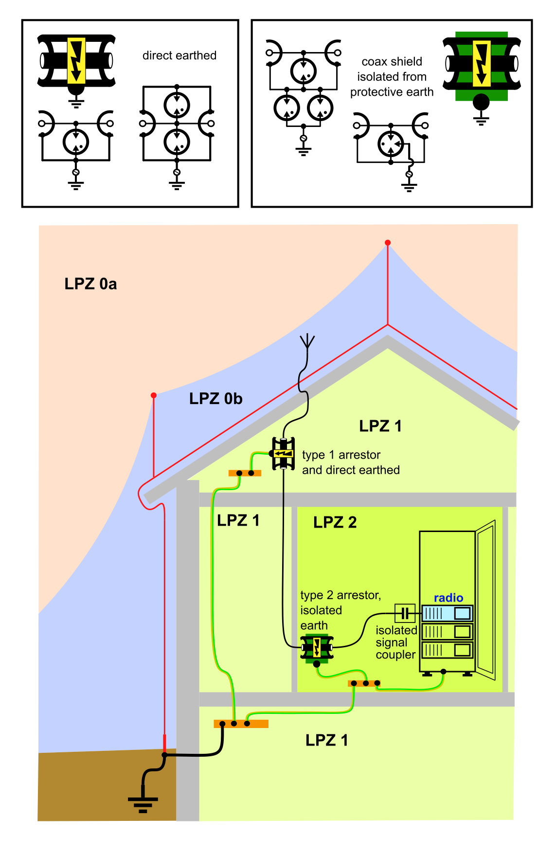
Multiple stage protection in a building
The first one sustains the (fraction of) raw lightning energy,
possibly coming down the coax downlink, when a lightning hits near by.
It may also help protect the active antenna's output.
The second one helps keep the tail end of the cable in a sane ballpark of voltage,
especially against EM-coupled (inductive) effects of a nearby lightning strike.
The arrestor clamps the resulting voltage to a level, that hopefully doesn't
set the receiver on fire, doesn't blow through the receiver box and into Ethernet
or other signal outputs, and if the gods are merciful, hopefully allows the sensitive
antenna input to survive without damage.
Note that the primary purpose of the outside LPS and the signal-level arrestors
is still to protect health and property against massive damage. A blown antenna input
is comparably minor collateral damage that cannot be completely avoided.
That said, in my practice, coax arrestors typically succeed in protecting
even the antenna input.
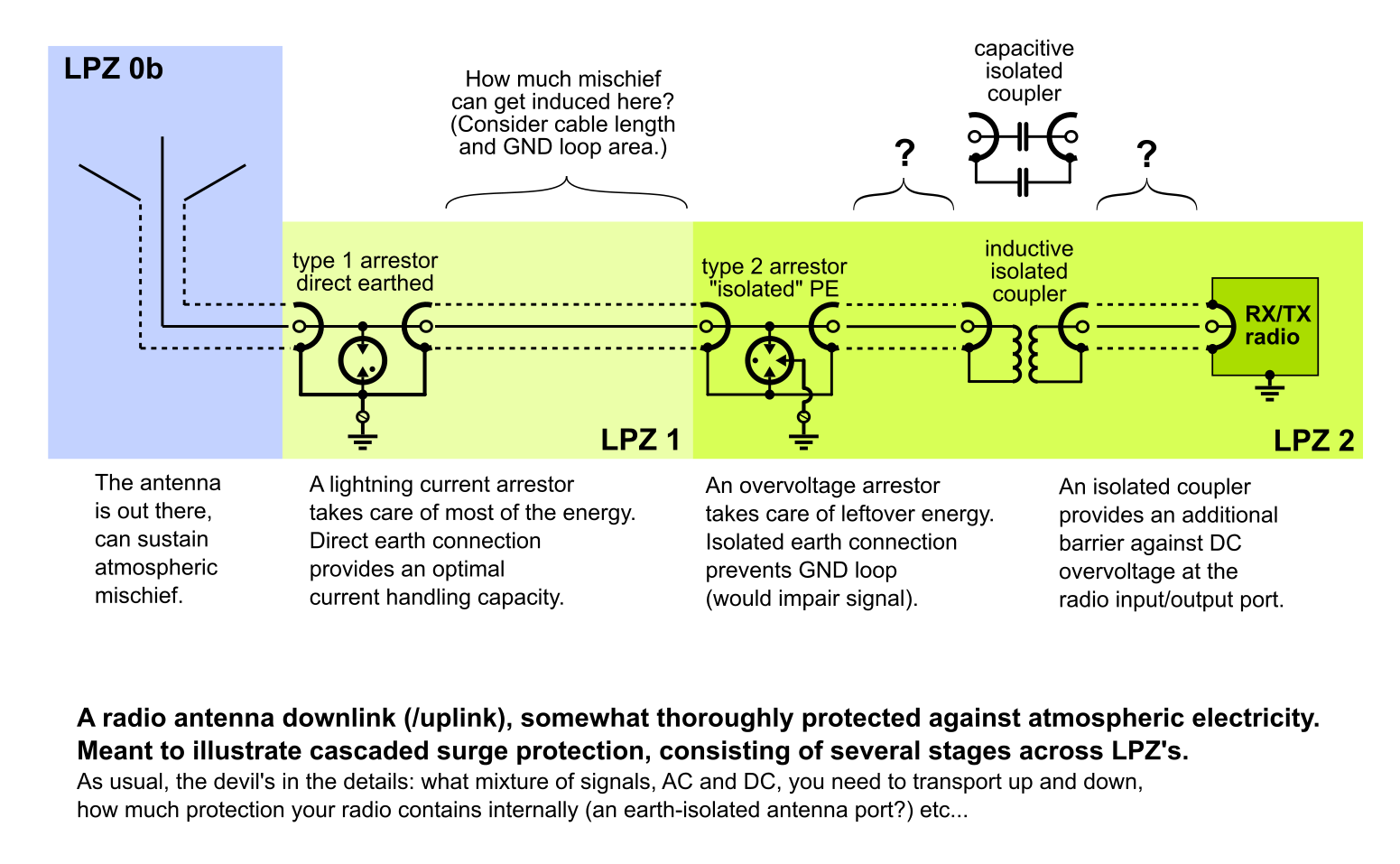
Antenna downlink signal chain / protection cascade, in detail
A combination of earth-isolated second arrestor + isolated input on the
radio has optimal chance of protecting the sensitive radio input.
For radioes without input isolation, prepend a direct-earthed (second stage) arrestor.
To learn some practical internal schematics, check with the various vendors of
signal-protection surge arrestors: Dehn, Phoenix, Saltek, ...
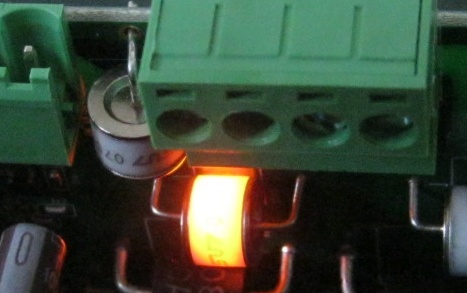
A spark gap glowing, during a continuity test using a few mA of current
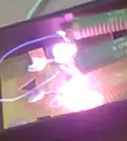
A surge arrestor under test, using a high-current test pulse.
Click for a video (with audio).
A closer look at some theory
Electric field intensity, gradient of potential
I'd like to consider homogenous materials / media, and blatantly ignore the many pitfalls and general untidiness of reality.
I'd like to focus on some neat properties of the theoretical electric field,
and draw some conclusions that are somewhat valid in real life.
Imagine two large, flat, parallel electrodes. If you apply voltage (differential charge),
the electric field in the space between the electrodes will create a linear, gradual scale of potentials,
stretching evenly between the two electrodes.
This will work in an insulator (with a homogeneous permitivity ε),
just as well as in a conductive material (with a homogeneous resistivity ρ).
The only practical difference is, that in conductive media, current will flow
(and the charge would need to be replenished by a current source / power supply).
And the answer seems to be: that one's implicit / forms the background.
If I were to create this in some FEM tool that only knew finite dimensions
and needed two electrodes to create a field, I would make the other electrode
either flat, very large and very distant, or I would make it a large and
hollow spherical object (not sure, I'd fear some adverse effects,
such as all the charge concentrating on the outside surface,
if the medium is an insulator = electrostatic scenario).
The point is, that when speaking of point charges and small
spherical objects modeling the field outside,
the formulas seem to abstract from the other electrode.
please note the beautiful effect, created by the electric field around small spherical objects.
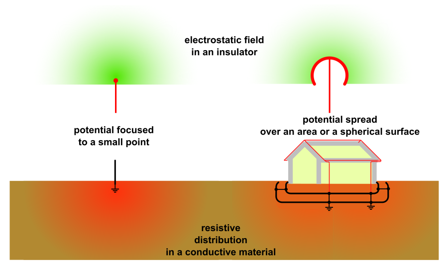
Distribution patterns of field potential in the air and in the earth,
depending on the size of charged object.
Please excuse the imprecise (linear) gradation of the scale,
as well as the schematic (un-realistic) pattern in the air part.
This is how far my mock-up in a vector graphics editor can go.
And, the gradient pattern should theoretically look the same,
up in the air and down in the earth (if some unrealistic
assumptions on material homogenity are met etc.)
And no, I don't mean "concentric arrangement of the linear scale".
(Although that's what my Inkscape gradients actually depict.
Well at least more of the scale is actually visible.
For an alternative picture, check out the Dehn bible on page 20.)
For a more mathematically correct curve,
behold the charts below. Generated in Maxima/Gnuplot and manually polished.
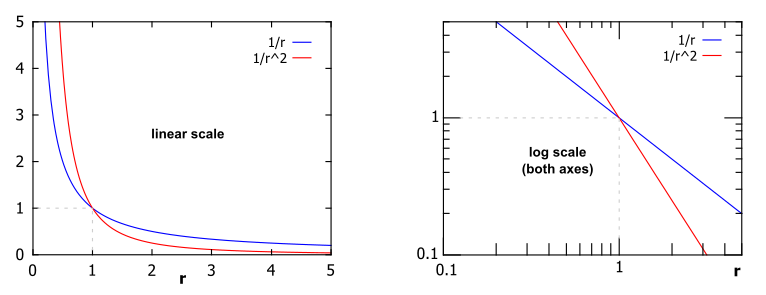
Votage (potential) and field intensity (gradient) in an X/Y plot
Horizontal axis: distance from charge center (spherical radius)
Vertical axis: blue: Voltage (potential), Red: intensity (gradient)
The sign (polarity) is subject to a further debate...
The "gradient" AKA field intensity, labeled capital E, being the slope of potential (voltage), becomes even steeper 1/r^2.
And, because neither the hyperbola, nor its quadratic 1st derivative, are defined for a distance of 0, an ideally dimensionless
point charge is really not possible. Some sources of wisdom actually use a single subatomic particle as a minimal example
= where our macro world meets quantum mechanics.
Also, "the other electrode" or "background" seems to be where the V = 1/r hyperbola reaches a V=0,
which happens asymptotically at r = infinity.
Consequences of gradient concentration, in the air
Larger spherical objects (where "large" is relative) do not leak charge
into open air so easily. This is because, geometrically speaking,
a sphere of substantial diameter has "evolved a step towards flat surface",
therefore the field gradient along the larger spherical surface does not reach
the insane heights observable around pointed objects.
See also the curve charts above.
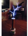
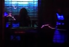
Dangerous toys...
In that sense, apologies for drawing my "air termination rods" with a small
cartoonish ball at the tip. "How large is still small" is relative :-)
It is just an illustration.
Consequences of gradient concentration, in the earth
I will add some basic math below.
The point is, that a smaller electrode provides a smaller "contact surface",
and the "effective conductor cross-section" in the surrounding resistive
material grows with (the square of) spherical radius.
Therefore, the closer you get to a point electrode,
the steeper the gradient of Voltage, per unit of distance (radius),
in the surrounding material (such as earth).
This is also why the step or stride Voltage is most dangerous
in a close vicinity of an earth electrode, and gets gradually smaller
the further away you are.
Again a larger earth termination electrode results in a lower
gradient / step voltage in its close neighborhood. Owing that to its
larger contact surface, and to the effect of effective conductor
cross-section growing with the square of spherical radius
in the earth material.
Also, imagine your earth electrodes exploding out of the ground, leaving neat little craters :-)
Field around spherical electrodes: the math
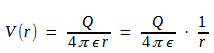
Potential/voltage in a static electric field in insulators
Q = the charge in Coulombs (extruded over time, you'd get current in Ampers)
ε = the nominal permitivity of the medium (insulator material)
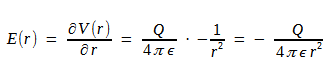
Intensity/gradient in a static electric field in insulators
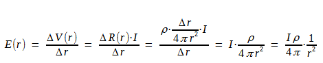
Intensity/gradient in a conductive material
I = the given current, in Ampers
ρ = the nominal resistivity of the medium (conductive material, posing resistance)
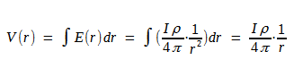
Potential/voltage in a conductive material
Inductive coupling
any cable, including signal cables, such as antenna downlinks, is subject to
inductive coupling of energy from the actual primary path of the lightning current.
An abrupt change of current in the primary conductor induces a voltage in the (primary and) secondary conductor.
Now... two wires, quite far apart... those will not be very effective as a transformer, right? Or will they? How do we grasp this?
You don't need windings, not even significant "loop areas": parallel wires are enough.
If you do have some loop areas in the system, these sure "help" = do increase inductive coupling, do make the adverse effects worse.
Given that the fastest (leading) current developments in a lightning strike happen on timescales of microseconds,
that would definitely be worth consideration, compared to e.g. 50/60Hz mains.
Parallel straight wires
Don't be intimidated by the number of symbols in the formulas below, it really boils down to just a few
variables, a handful of constants, and a wee bit of extra complexity to account for non-ideal geometry in real life.
To give credit where credit is due, AFAICT, the formulas come from publications by gentlemen Rosa and Grover.
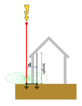
So: a straight wire has inductance.
Two straight wires in parallel therefore share a part of their surrounding magnetic field, thus comprising a transformer.
Albeit a non-ideal one. The point of this chapter is, to put our finger on what "non-ideal"
may practically mean, and the ballpark of what voltage can result at the secondary side.
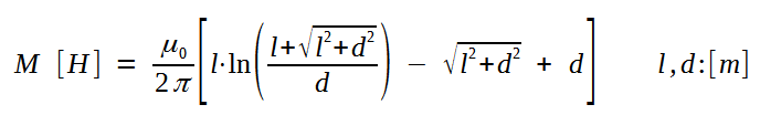
Mutual inductance of parallel wires
The two input variables are:
l = length of either wire, they're both the same length
d = the spacing between the wires.
As for units, both inputs are expected in meters.
The output that we get is an inductance, in units of Henry.
A so-called mutual inductance,
between the two "windings" (wires) of our transformer.
Mutual, hence the letter M.
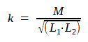

That's simple: there's another formula from gentlemen Rosa and Grover.
If this gives you a deja vu, you are probably right. In their publications, the two formulas are "on the same page" (or thereabouts).
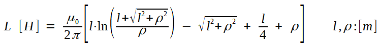
Self-inductance of a straight wire
l = length of the straight wire
ρ = radius of the wire
As for units, both inputs are expected in meters.
The output that we get is a plain old inductance, in units of Henry.
All of that combined results in a k of about 50% .
And because it's l/d that matters most, you get a similar result e.g. for length = 10m and spacing = 1 m.
Only in the later stages of redacting this howto, I've found this same picture in
The Dehn Bible on page 21.
Speak of reinventing the wheel, sheesh... well at least I know I've done the maths right.
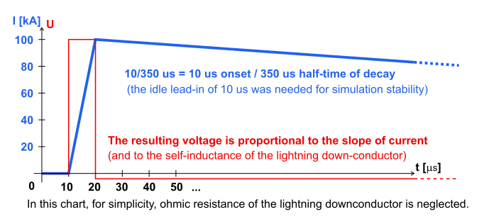
An explanation to the following sims. (Note: the colours here have different meanings.)
0;0
5e-6;0
1e-5;0
1.5e-5;5e+4
2e-5;1e+5
3.7e-4;5e+4
7.2e-4;2.5e+4
1.16e-3;1.25e+4
1.51e-3;6.25e+3
1.86e-3;3.125e+3
2.21e-3;1.5625e+3
The first column is time, the second column is value (instantaneous current).
Yes I have extended the trailing lead-out quite a bit in the input data... (unnecessarily so).
Also note that the lead-out in my sim is linear, while the "half-time" specification would rather
hint at an exponential decay model. Consider it a suggested mental exercise for your homework,
to guess what the resulting voltage curve would look like in that section.
Remember: across an inductor, the voltage is a slope = first derivative of current. ΔI / Δt is what matters.
To have the simulation produce "nice" output, I specified L1 = L2 = 10 uH and a coupling coefficiet k = 0.4 - as can be seen in the schematic screenshots.
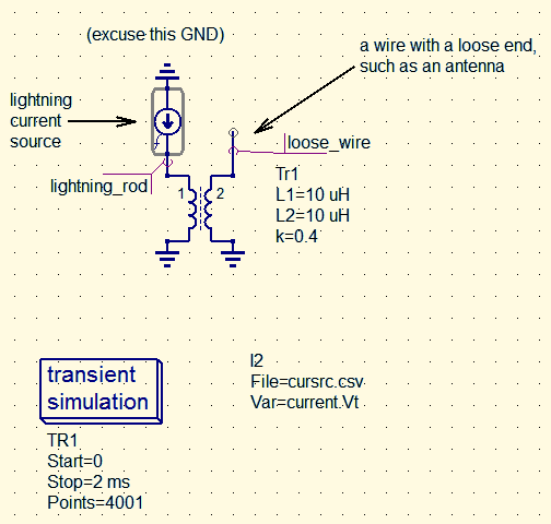
Simulation #1 schematic: inductive only (the downconductor has 0 ohms resistance)
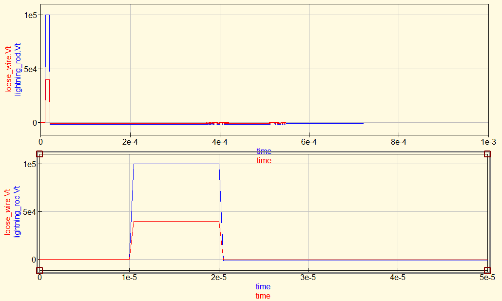
Simulation #1 result plot: inductive only (the downconductor has 0 ohms resistance)
Blue: voltage at the primary side hot end (LPS air termination)
Red: voltage at the secondary side open ended
Timescale: 1 ms (upper chart), 50 μs (lower chart)
Unit of vertical axis: Volt
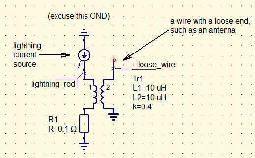
Simulation #2 schematic: inductive with resistance in series
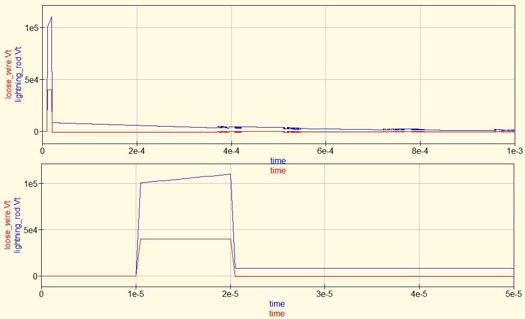
Simulation #2 result plot: inductive with resistance in series
Blue: voltage at the primary side hot end (LPS air termination)
Red: voltage at the secondary side open ended
Timescale: 1 ms (upper chart), 50 μs (lower chart)
Unit of vertical axis: Volt
Now... is the exercise above, with straight wires, any use, after all? Is this relevant to our practical scenarios?
Do we really care about the difference of potentials, at two ends of a wire, that are many meters apart?
In our practical circumstances, in a building, we are most likely to encounter a loop.
In terms of EMI induction, a loop that's equal to a proper turn of a coil.
We will be concerned about a voltage differential between two different wires or cables,
arriving from two different directions to a particular common location.
Typically, at the antenna input of a radio receiver,
where we have a local Protective Earth, and a coax downlink will arrive from somewhere up there upstairs,
where the coax shield has contact to another branch of the PE tree. This is our scenario - not a straight wire,
but loop area.
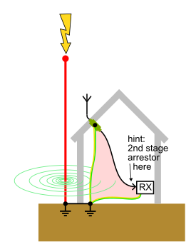
The Dehn Bible actually mentions this scenario on page 21. It also quotes a conveniently simple and straightforward formula, making direct use of the "mutual inductance" (M):
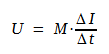
Arguably, it can hardly get any simpler than that :-) Probably the best clarification of what the mutual inductance is good for.
On the same page 21 with the formula, the Dehn Bible has a convenient nomogram, giving you the values of M for various geometrical arrangements of the LPS downconductor (straight wire) and an arbitrarily placed wire loop.
In various low-profile websites I have observed a corresponding formula along these lines:
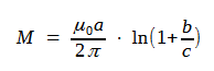
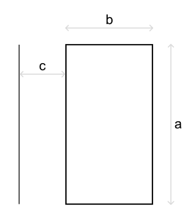
That seems even simpler than Rosa+Grover.
All the formulas in this chapter are in SI units, BTW = meters, Henrys, Volts, Ampers, seconds.
A secondary loop taking energy from a primary wire has one interesting property:
the turns ratio is greater than one. This setup transforms voltage up.
The Dehn Bible on page 21 also has an example calculation,
where the voltage levels seem to come out correspondingly higher than my
guesstimate above for parallel wires.
Note that the calculations in this "inductive" chapter almost completely omit resistivity of the outside LPS. It gets debated elsewhere in this howto. In reality, inductive and resistive effects (contributions to peak voltage) will add up.
As for inductive effects, also note that a lightning strike is not that nice smooth waveform, of 10/350 or 10/1000 μs or whatever is used in lab tests. The arc produces a significant power of RF interference - which also gets induced by the mechanisms outlined above, and worse: some of the RF power is "in band" to your radioes and modems, cannot be easily removed by arrestors, and will probably pass through any passive galvanic isolators (transformer-based or capacitive). C'est la vie.
In practical circumstances, you cannot calculate a particular level of coupling, and some particular induced voltages. There are several reasons - pretty much none of the inputs are very deterministic. The energy of a lightning strike is a statistical distribution. The state of various conductive joints in the outside LPS is also somewhat random and may develop in time. The path of PE and signal cables through a building can be complex and not fruitful to model.
Hence the approach of lightning protection norms: aim for the reasonable worst case energy, break the problem down into manageable chunks, define envelopes of the level of harm that you need to protect against, and construct the complex LPS along the coarse estimates and according to empirical best practices, to sufficiently tackle the level of threat/risk evaluated.
The Lightning Protection Guide by Dehn.
Should the link drop dead, here you are a local copy for historical reference.
The book, currently at 3rd edition, is almost 500 pages long, and deserves a list of references to particular pages.
Straight from my scrapbook:
| Page | topic |
| 15 | Chapter 2: what is lightning |
| 20 | Gradient of voltage in earth, depending on distance from the point of lightning strike |
| 21 | Induced voltage in conductors (loops) in the vicinity of a lightning path |
| 34 | Flash density stats in Germany (a map) |
| 54 | Kirchhoff's Law, demonstrated on the outside lightning downconductor network (mesh) |
| 64 | LPS architecture (the Parthenon picture) |
| 64-68 | Rolling sphere (dimensioning criteria on page 25 and 90 too, including mesh size) |
| 69-71 | Cone model |
| 73 | Sheet metal thickness preventing puncture |
| 75 | Isolated (separated) air termination rod |
| 95 | Downconductors - spacing |
| 97 | Downconductors - maximum temperature rise, based on material and cross-section |
| 104 | High-volt isolated downconductors |
| 119 | Step/stride voltage gradient in earth |
| 122 | Resistivity values for different soil types / geology |
| 128 | Earth resistance examples based on soil types and termination length |
| 122-129 | Earth resistance and resistivity, in general |
| 149 | Dimensioning of earth electrodes |
| 150-156 | Separation distance (the reference on page 102 is related to HVI conductors) |
| 178 | Equipotential bonding at the base of the building |
| 187+ | Protection of electronic systems, LPZ, 62305-4: chapter 7 starting on page 187 |
| 199 | Avoiding GND loops between buildings |
| 292 | Minimal parameters and practical construction of earth electrodes |
| 293-295 | Example: Antenna on a roof, with an isolated/separated "air termination", and arrestors grounded inside |
| 345-349 | Example: LPZones on a wind turbine |
| 358 | Example: LTE radio tower |
| 371 | Rolling sphere method versus protective angle method for determining the protected volume (the bottom picture) |
| 452+ | Yachts |
The Dehn Catalogue of Lightning Protection / Earthing
Should the link drop dead, here you are a local copy for historical reference.
Kniska is a publication in Czech language
by Jan Hajek of Dehn CZ and Dalibor Salansky of LUMA Plus s.r.o.
Written in casual style, but thorough, I hardly dare to call this an introduction.
Obviously a promotional material, but nice. Contains some interesting pictures/examples that I haven't seen elsewhere.
The formulas on conductor self-inductance and mutual inductance of two straight wires
come from a somewhat ancient source:
A book by Frederick W. Grover, called Inductance Calculations: Working Formulas and Tables.
It has been re-printed several times since its initial publication in 1946.
Apparently, there are prints in the public domain that predate the book:
bulettins of the Bureau of Standards from 1908 and 1916, co-authored by
Frederick W. Grover
and Edward B. Rosa.
They were colleagues and collaborators, and F.Grover took over the torch after E.Rosa died in 1921.
The formulas as published in those original prints did not pay much attention to mentioning
the physical units used for input and output - apparently, centimeters and nanohenries
were a popular choice. The formulas as quoted in this howto
have been scaled
to SI units (meters and Henries). It is not surprising that Grover and Rosa
originally did not stick to SI units in their day and age, as the
SI system has only been standardized in 1960.
Dimensioning of earthing system in HV switchgear
-- a master's thesis by Roman Bursik. The paper is in Czech (unfortunately for the global audience).
Contains a neat example of a substation earthing grid on the very last page,
and e.g. a table of resistivities for various types of earth.
Where I work, Vladimir Brok has been our supplier of surge arrestors,
on and off for the last two decades or so. Born in 1945, he graduated
as a Dippl.-Ing. of RF/transmitter technology, then spent some two decades
working in govt-run high-Volt test labs, followed by three decades
freelancing as a maker of surge arrestors for signal transmission lines
of various sorts (winding up the business for good, just about now).
He has spent many hours with me in spoken conversations and e-mail
exchanges, educating me about the principles of arrestor design
and application-side best practices.
My favourite quote from him:
"If it gives a loud snap, a flash and a puff of smoke,
it means that the test has been carried out :-)"
Regarding the substation grounding grid, I've been pointed to this
by a friendly commentard in a benign forum on... system administration :-)
Apologies to my global audience, the linked text is in Czech.
The nick M D is not unknown to me in real life - a seasoned practitioner
in substation automation, well versed in the High-Volt side of things
and in industrial IT+networking. In that IT forum, upon my off-topic troll prompt ;-)
he didn't hesitate to initiate me and the rest of the audience. He started by
explaining various things relatively on topic, quoting from the IEC\EN 62305,
and upon my prompt, went on to refer me to some intra-corporate norms
of our domestic utility companies in the high-volt business...
I recall several other fleeting conversations
with people I met on random occasions during the years:
Jiri Janda sr. of JJJ-sat, who used to sell and install TV+SAT gear back during the nineties...
Several people in the electric power transmission and distribution companies (our customers at FCCPS)...
Electricity inspection engineers who come regularly to give us training...
Etc.
This scribble by: Frank Rysanek (rysanek [AT] fccps [dot] cz) (8/2023)