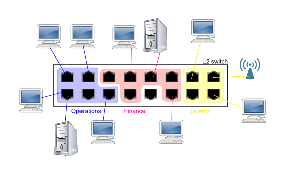

Why VLAN's:
Rather than keep a messy haystack of various small boxes where
one size never fits all, you may dream of being able to "compartmentalize"
a bigger switch machine into smaller separate networks that don't
know about each other, don't share any traffic, don't see each
other's traffic (cannot sniff it), cannot launch attacks against each
other - yet as an admin, you'd be able to allocate individual ports
to this or that network.
Bravo - you've reinvented the basic VLAN's.
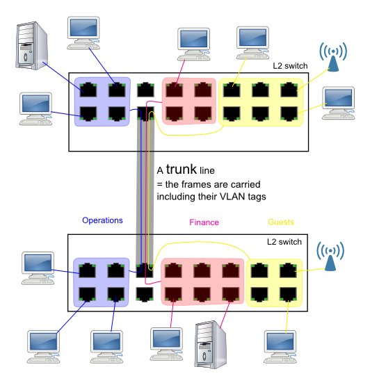
Suppose that one box is not big enough, and you want to spread your VLAN's across several floors or buildings or rack cabinets... One switch of appropriate size per floor. Doesn't that sound interesting?
Well there you have it.
Actually you could do this without VLAN trunk ports, but you'd waste
several "untagged" aka "access" ports on each switch (per floor)
for dedicated per-vlan interconnects.
With trunk ports, you can also "share backbone bandwidth" among the VLAN's. Hence the trunk ports often have more bandwidth (higher link speed) than the "access" (untagged) ports.
Obviously you're not limited to just two switch boxes. You can daisy-chain as many as you want - modulo practical STP convergence/stability, and practical administrative manageability of a huge network.
Now... what if we need to route IP traffic between the VLAN's? Or, connect them all to the Internet. For practical routing purposes, the VLAN's are just separate Ethernet LAN's. Your router needs to have a separate interface into each VLAN.
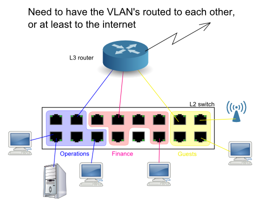
Ahem... yes of course there is a better way. You don't need to waste so many untagged access ports. Instead, you can plug a trunk into your router.
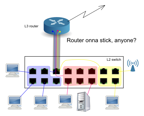
That takes a single port on the switch. The condition is, that your router must be able to handle the trunk = must know how how to deal with the VLAN tags = must be willing to have VLAN "subinterfaces" configured on its Ethernet interface. Again for practical routing purposes, the VLAN subinterfaces behave just like dedicated interfaces in the router.
What? A switch is per definition an L2 device. At L3, the respective packet forwarding device is called a router. An L3 switch sounds like nonsense.
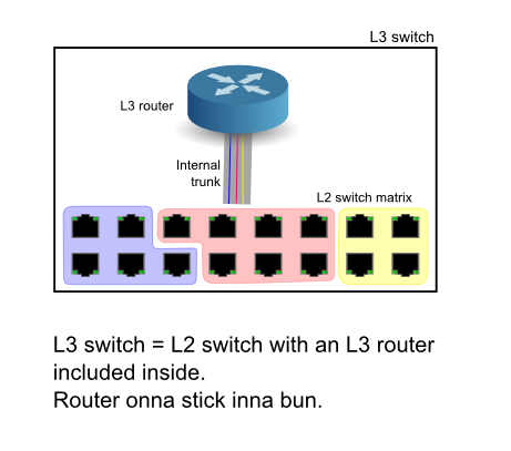
Well... sort of. "L3 switch" is a biz buzzword for a switch box with an integrated router. The router has an internal trunk interface (the "stick") into the hardware switch matrix in the same box, so it doesn't have to occupy an outside port. The internal trunk can be made pretty beefy.
It gets better - an even tighter integration is possible:
the first step is what Cisco called MLS around the
turn of the centuries: the router only gets the first packet
in a flow (such as a TCP SYN packet, but it also works for UDP
for instance), makes the routing decision, the switch matrix makes
a note of that, and switches the rest of the flow autonomously,
based on where that first packet got routed.
By now, that early stage is mostly history. Serious router hardware
now understands enough of IPv4 to be able to route it and filter
it altogether without CPU-based processing.
Let's start with a recap of relevant framing and encapsulation. Do you know the Russian "matroska" (matrioshka) toy?

If you understand this recursive doll, you understand
data encapsulation in Networking. Well sort of.
It always starts with a buffer loaded with bytes of payload
data. In the case of TCP, the payload buffer is conceptually
a chunk of a longer data stream, as TCP is "session-oriented".
This bare payload forms the basis of packets (datagrams,
frames - your vocabulary may vary based on your background).
The mechanism of wrapping the data in envelopes with several
stacked layers of "headers" is called "encapsulation".
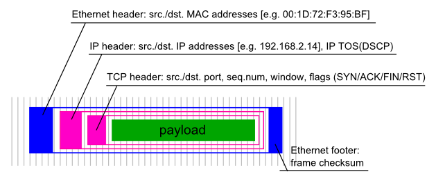
Actually in case of Ethernet, the outer-most packet also has
a trailing "footer", holding the frame checksum.
Ever heard of the ISO/OSI layered networking model? In this
generic model, Ethernet belongs to Layer 2, IP belongs to Layer 3
(although TCP/IP-based Internet was probably not what the folks
at ISO/OSI had in mind when coining the layered model, their idea
was more like X.25 running over X.21 or V.35 or G.703).
Allright allright, time to get back on topic... I've promised to you a VLAN tag. Here it goes:
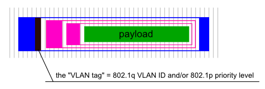
Note that the VLAN header is not another wrapper around an Ethernet frame. It's actually an optional field inside the Ethernet header structure. I've borrowed this picture from Cisco:
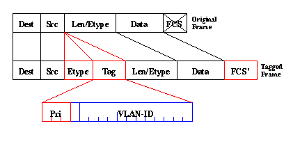
Note that the "VLAN tag" actually contains two data fields:
One catch here is: how to create an Ethernet frame that doesn't
belong to a VLAN, but has a non-default (non-zero) priority?
The answer is: it must have a VLAN tag, but contain a 0 (zero)
for VLAN ID. The only purpose of the tag here is to carry the
priority information. Other than that, the packet is to be considered
"untagged" in the sense of belonging to any particular VLAN :-)
A practical implication is, that VLAN-aware switches may replace
this "zero VLAN ID" with an actual VLAN ID on ingress, just as
they would do with a truly untagged packet. On Egress = on a terminal
"untagged" port = on exit from the last VLAN-aware switch,
the packet may be stripped of the VLAN tag altogether (including
the possible priority information). Subject to switch configuration,
switches may also elect to set their own priority value on ingress
= to override the original priority level...
Just in case you were wondering (like some of my customers)
what the difference is between configuring proper VLAN's,
and just using different subnets on a common ethernet...
Yes there is a difference:
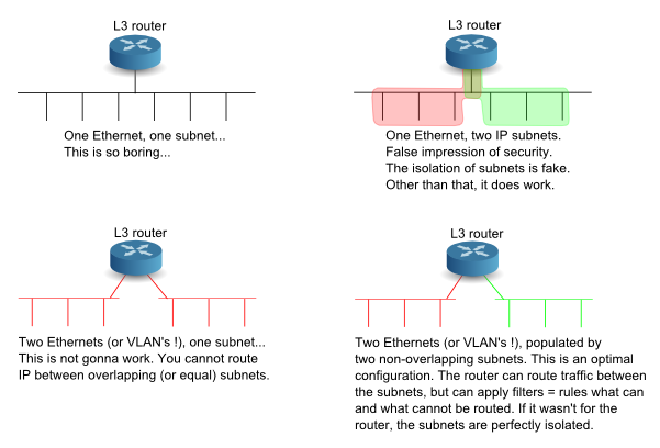
With just subnets on a common LAN, there's nothing to prevent
a rogue client to change an IP address and start talking to the
wrong subnet. Better yet, a rogue client can change its MAC address
to pass through a possible MAC address filter or a static ARP rule.
Whereas if you configure proper VLAN's for the "host groups"
that you want to separate, the VLAN's are pretty much impenetrable.
A rogue client may change its MAC address, but that doesn't help
him to break out of his own VLAN within a switch (at L2).
If you configure VLAN's, and you want to run TCP/IP among them,
it's actually appropriate to use a different subnet for each VLAN,
which will allow you to use a router (= the right device for the purpose)
between the VLAN's.
The open 802.<something> standards, namely 802.1Q for VLAN's combined
with 802.1D for the Spanning Tree Protocol (STP), specify that a switch
shall run a single instance of the Spanning Tree Protocol, encompassing
all the VLAN's.
Which has principal downsides.
Consider a network with VLAN's, where you want to differentiate
what VLAN's will flow over which trunk paths. In principle,
this is perfectly legit, as an operational requirement and
as a technical configuration.
But, consider what happens, if you combine this with STP.
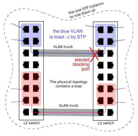
I've actually managed to produce this scenario by mistake in a lab setup, where I had two switches (DUT's) side by side, each had an untagged connection to my LAN for management, and I created a trunk between them, dedicated to some specific traffic (PTP) that I did not want to seep into my office LAN. The picture above tells you the precise result.
Unsurprisingly, swich vendors have come up with a remedy. Cisco has a proprietary extension to run per-VLAN instances of STP (called PVST+), and an alternative setup, called MSTP = Multiple Spanning Tree Protocol, was specified in 802.1s (later merged into 802.1Q-2005).
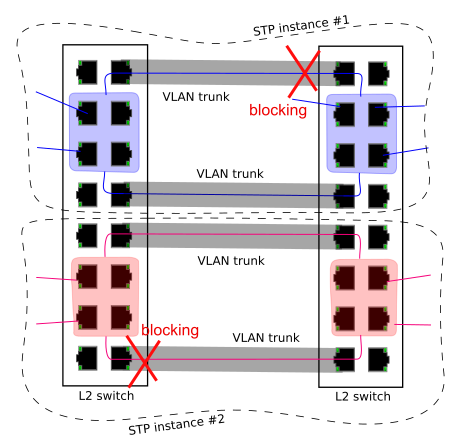
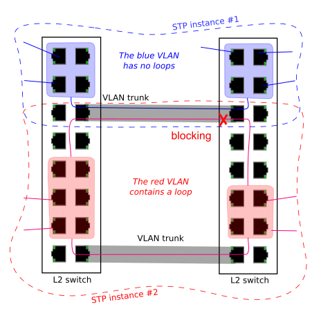
In pretty much the same vein, switches traditionally run
a single MAC address table (aka CAM table, aka FDB = Forwarding Database),
shared by all the VLAN's - which has security and transparency
implications. Namely, it's possible to force a switch to re-learn
a MAC address to a "wrong" port (= away from the correct port)
by sending a packet with the "attacked" MAC address as a source
address in the attacking frame (= MAC address spoofing),
from an untagged port belonging to a different VLAN.
I.e., this defies the original design objective of VLAN's,
which is perfect separation of traffic.
The attack should not yield access to the attacked VLAN
= it's a "denial of service" attack.
And even worse, there are actual Ethernet-based protocols out there,
albeit exotic and ancient, that use a fixed MAC address as a source,
e.g. to designate a protocol master. Guess what happens if you try
to run this through several simultaneous VLAN's,
on a switch that has a global shared FDB.
And, this is exactly why some switch vendors have implemented per-VLAN forwarding databases, allowing the same MAC address to exist independently in parallel VLAN's.
In some switches, it's actually possible to configure a port to forward both tagged and untagged traffic (the configuration is per VLAN). It's definitely possible in the Linux OS.
Actually the aforementioned "single STP instance", if configured, operates using untagged frames (also called a "native VLAN") on trunk ports that are otherwise principally tagged... and there are many other protocols that run untagged on a physical port, even if the port is otherwise used for dot1Q VLAN trunking. LLDP, LACP, PTP...
All of this points to an ugly truth:
while the more user-friendly switches tend to let the admin work
with the VLAN's at some comfortably abstract level, the technical
reality under the hood is much more frugal: VLAN's are implemented
using a cascade of "filters" that control the addition or stripping
of dot1q tags and the mapping from which port to which ports the
"VLAN-flavoured" packet at hand is to be forwarded.
Some switch vendors actually require the admin to participate in these
ugly details of the VLAN's a little deeper: the admin may be required
to configure (separately) some of the following:
To allow for scaling, or to allow for transport of a customer's VLAN-tagged traffic through an Ethernet-based provider backbone, some switch vendors allow "Q in Q" = layered dot1q tags.
Some vendors have implemented a mechanism to further restrict visibility among individual network nodes within a classic VLAN (within a switch, not sure if cross-switch). The point is, that e.g. a default gateway can talk to anyone, but the other nodes (clients/stations/desktops) cannot talk to each other - only to the gateway.
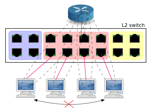
Different vendors have different ways of implementing this.
On the outside, by their configuration style, private VLAN's may feel like intra-VLAN "groups"
(where a member can overlap) or second-order VLAN ID's (some call them PVID for
Private VLAN ID). I.e. it is something slightly less painful to use compared to
e.g. MAC-address-based access-lists.
Not much point in linking directly to the IEEE papers and IETF RFC's...
A more detailed introduction by Cisco
...or just use Google...