By: Frank Rysanek of FCC prumyslove systemy s.r.o. [ rysanek AT fccps DOT cz ]
Shortcut to version 1 with a PCB
Let's start with a schematic to get you intrigued :-)
A few months ago, I lobbied my employer into buying me an oscilloscope,
because it's convenient to have one in our PC assembly and repair workshop.
Actually it's a relatively inexpensive external USB oscilloscopey box,
which you have to connect to a PC to get the display and control knobs.
To me, that alone is hardly a disadvantage :-)
The box is an M595 by ETC.
Okay, it probably doesn't have all the bells and whistles of a true
stand-alone 'scope, but it does give quite a bang for the buck:
for 1000 EURO (at the time of this writing, i.e. January 2010) you get
As a kid some decades ago, I've read that you can measure reflections
in RF cabling using an oscilloscope and a pulse generator.
For me, christmas has come early last year :-)
And, one of the applications I knew I wanted to try someday down the road,
was to build a simple probe for basic reflectometry in metallic cabling
of all sorts. As soon as time allows. And indeed the time has come.
Obviously I was wondering, what would be the easiest way to build
a pulse generator with sharp enough edges, to match the capabilities
of my new scope. Discrete transistors are always the last resort :-)
I googled for some comparison tables of 74<something> logic families
currently on the market, and I found out that 74AC was rather promising.
Its switching times are in the low nanoseconds range (excellent slew rate)
and its output drive capability allows you to drive a 50Ω transmission
line maybe even with a single gate.
I wanted to generate the narrowest possible pulse, with the individual
pulses spaced far enough apart to allow measurements of any reasonable
length of cable. The duty cycle is also a matter of load = heat dissipation
in the output stage. I ended up setting the main oscillator to 1 kHz
(I'll never need to measure 100 km of cable), which is then fed into
a single-shot pulse shaper that produces spikes about 40 ns wide.
That means 40ns pulses spaced 1 ms apart.
The circuit can optionally be jumpered for a 1kHz rectangle with
a 50% duty cycle (the generator of spikes gets bridged).
The oscillator's and single-shot's own output edges are not razor-sharp.
I needed additional gain stages (gates) to sharpen the edges.
I also needed a few gates to connect in parallel, to comprise the
output booster / line driver.
The maximum number of inverting gates in a single DIL14 74AC package
is available in the "hex inverter" chips, 74AC04 (normal trigger)
and 74AC14 (Schmitt trigger).
I ended up using a 74AC14 (Schmitt trigger) for the timing and shaping
stages (where the "Schmitt hysteresis" improves "depth" and sharpness
of the oscillation), and a 74AC04 (all six gates in parallel)
for the output booster (I was afraid that schmitt triggers
might be harder to mix and match in this position).
The output of the booster (power stage) has a reasonably low impedance, and is matched to the transmission line using a resistor in series. I included four different resistors, selectable by a jumper, to accomodate the typical cabling impedances of RF coax cables and twisted pair cables. Note that the precise matching at the transmitter is not all that important - if you want to estimate the impedance of an unknown cable, just try some value at the transmitter and focus on the far end reflection. The far end is where you try to achieve the optimum matching, by adjusting the terminator resitance - it is the far end reflection that's well visible (unlike a local mismatch at the transmitter, which causes just a bit of glitching at the pulse edges).
The connector labeled "Oscilloscope" is DC coupled (hardwired) to the pulse generator's output, after the nominal impedance resistor bank. The connector(s) going to the cabling are "AC coupled" via a capacitor, so that you can perhaps probe a line carrying phantom power. The capacitor can be bridged (shorted) by a jumper cap in order to achieve hardwired DC coupling.
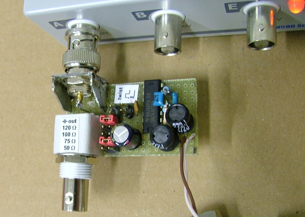
...she's a hack of a probe...
The scope has a BNC female as its input. The reflectoprobe is mechanically a small "passthrough" box that plugs straight into the scope's hi-Z input, thus avoding any universal scope probes, which tend to have limited bandwidth. Therefore, the reflectoprobe has a BNC male towards the scope, and a BNC female towards the (coax) cabling. In parallel to the cabling-bound BNC, there is a 2.54mm pin header (two pins, like a jumper) for direct attachment to twisted-pair cabling. Actually I have a pigtail with the corresponding straight connector crimped on, which I can easily attach to wiring terminals of RS485 busses etc.
I also have a set of connector conversion plugs (BNC to N, BNC to IEC, BNC to F etc).
The easiest way to power the reflectoprobe is from the computer's USB port. The consumption of the probe is negligible. (Note that the M595 has a mains power adaptor, because its consumption is too much for a USB port, especially on Notebooks. Based on previous experience with various USB gadgets, this is in my opinion the right and fair solution.)
I have a small bag of beefy ceramic caps cannibalized from a scrapped motherboard. They're 10 uF, probably rated at 10V or even 6.3V voltage. They're a perfect component for PSU decoupling, and I also used them in place of the output AC coupling cap (note that it would be more appropriate to use some higher-voltage caps in this position :-)
A couple things you can do with the reflectoprobe:
Finally, here are a couple of example waveforms:
Probe jumpered for 50 Ohms, no cabling or other load attached
Probe jumpered for 50 Ohms, loaded by a 50 Ohms terminator straight on its output (no cabling)
12 m of CAT5 UTP open-ended (unterminated)

12 m of CAT5 UTP terminated with 100 Ohms
12 m of CAT5 UTP terminated with 120 Ohms

20 m of RG58 coax open-ended (unterminated)

20 m of RG58 coax with an active antenna attached at the end (unpowered=inactive)
And a photo of the whole toy set:
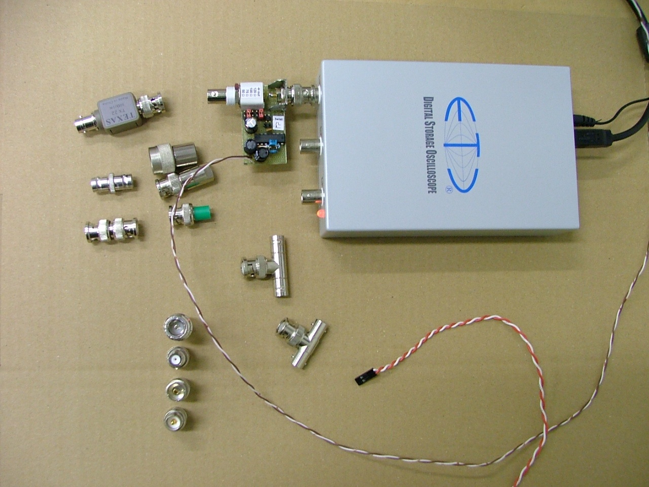
An ETC M595 with the reflectoprobe attached
Professionals in the area will probably grin at the sight of my probe.
Besides being an ugly hack, the probe is basically a time-domain device,
and a true Pro swears on frequency-domain reflectometry (as far as
metallic cabling is concerned), because that allows you to send your
probe through bandpass filters at the target frequency, or to measure
the frequency response / phase response / standing wave ratio
of any complex topology of transmission lines, filters, antennas etc.
And, a true Pro is used to thinking in terms of spectra,
rather than pulse shapes. Readily displayed on his 10000 EURO SiteMaster.
Actually I've seen a simple sweeping-based frequency-domain probe
with a USB attach, don't know the price.
Ah well... I still love my 10$ baby :-)
A few years later, I have updated my design somewhat.
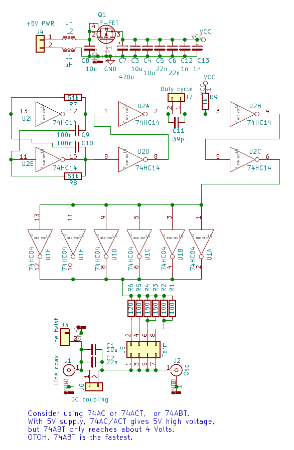
(Click to download the schematic in PDF)
Mind the P-FET in the power supply input. This works as polarity reversal protection,
for the pulse generator board itself.
Note that this alone won't protect you from a short between USB +5V and GND,
if you use USB to power this gadget, you use an unkeyed header, you flip the pins,
and you have all the grounds connected through the scope to the source of +5V
(a PC or the scope itself).
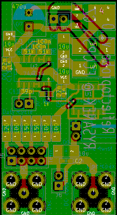
(Click to download the Kicad project, including exported gerbers.)
Based on my build of this v1.0, I'm wondering if I should lower the capacitance of the output node, which is probably too high. Maybe remove the ground plane from underneath the switchable resistor bank... I figure that it might decrease the ringing on the edges somewhat.
Actually the PCB is out of date anyway, because the particular model of a BNC connector is now obsolete (TE Connectivity 5-1634556-0), and its footprint is unique...
So it's probably time for v1.1...