


char




edge


edge




By: Frank Rysanek of FCC prumyslove systemy s.r.o. [ rysanek AT fccps DOT cz ]
There seems to be a common wisdom saying that RS485 runs over just about any cable you happen to have around, and termination / grounding doesn't matter much. This article provides some practical observations / oscilloscope plots, implied by such approach. Finally, the highly theoretical transmission line mumbo jumbo (and conclusions, arcane termination networks and whatnot) are confronted with reality - practical findings as to what does actually help when an RS485 network just doesn't work. And no, common-mode termination is not the magic bullet :-) The work was guided and inspired heavily by the Circuit Cellar articles mentioned in the References.
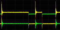
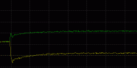
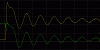
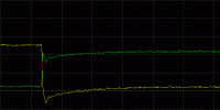
Let's start with some pictures without much explanation, to get you interested. The boring theory follows.
| 1. | 2. | 3. | 4. | 5. | |
| Term. |  |
 |
 |
 |
 |
| Whole char |
 |
 |
 |
 |
 |
| TX on |  |
 |
 |
 |
 |
| Rising edge |
 |
 |
 |
 |
 |
| Falling edge |
 |
 |
 |
 |
 |
| TX off |  |
 |
 |
 |
 |
This is how it all started in my case: I work as a service techie for a local distributor of some embedded PC's. From one recent delivery of a new model, we got several pieces returned, with problem descriptions relatively vague ("our software doesn't communicate") but all the more urgent - the deadline was burning bright for our customer, an automation systems integrator. The issues clearly revolved around Modbus/RTU running over RS485.
My general approach to problems is to try to reproduce them in the
lab first, and in the process, get the hang of the technical area of focus,
maybe do some follow-up reading, figure out some test methods,
hack together some reusable probes etc. In other words, do some
thorough technical howework before I possibly depart for the customer's
field site.
Ironically, but not really to our surprise, our hardware behaved
fairly well in our lab. Under scrutiny, the UART's did show some
marginal misbehavior (difficult to reproduce), but no complete
show-stoppers of the sort described by our customer.
So I decided to start by taking a hard look at RS485 itself,
for the first time in my practice.
I actually have a nifty new USB oscilloscopey gadget, which I've recently
complemented by a simple
homebrew "refectometer probe"
(pulse generator)
- I figured it was time to give them a whirl. Others in my place would
certainly suggest a jumbo mug of coffee, except that I don't drink that
- but I still have to admit that I did sit back and think a lot.
My employer company doesn't really install RS485 (nor SDH/PDH nor CAN) in the field, so I don't have the genuine shielded/twisted cabling footage in stock. When testing RS485 gadgets in our lab, we tend to use CATx cabling (commonplace in our computer shop). Usually we use CAT5e UTP, or sections of single pairs extracted from that - but I also have some CAT7 S/STP left over from the last Ethernet upgrade (used it for the "gigabit backbone").
So I cobbled together a basic RS485 network: a 3rd-party
Modbus/RTU slave (some discrete input module),
some RS232 and USB converters for "eavesdropping" on the data
via other computers, attached the culprit box as a Modbus master,
added the basic rule-of-thumb termination (120 Ω at each end),
and connected the scope probes.
I have a dual-channel digital scope
(cheap USB thingy) with un-isolated un-balanced (single-ended) inputs,
so I just attached the scope probes' ground clamps to the RS485 master's
signal ground terminal and hooked up the probe tips to RS485 DATA+ / DATA-.
The bus cabling consisted of maybe 14m of CAT5e UTP, in a coil on the
lab table. There were several short stubs (50 cm or less) at the ends,
but I figured that those wouldn't matter much (and I was right).
Initially I didn't provide a signal reference ground for the bus
(our vendors of RS485 equipment do not stress that point).
So the various nodes either had a reference ground from the
mains protective earth, or had no reference ground at all
(some of the nodes were earth-isolated at the PSU or at the 485 port).
The line parameters are 9600 8N1. I actually started with just
hyperterminal at the several computers attached to the bus,
and kept typing characters at the various terminals,
to see if the data was getting through.
It was immediately clear that in my lab setup, the data was getting through just fine (as expected - it works even without terminators). Something did raise my eyebrows though - the oscilloscope traces.
The signal edges on my initial RS485 bus were wobbling frantically. What the hell, I've got the recommended terminators on...? Back to the drawing board = transmission line (TML) theory. I have some basic RF background on coaxial and historical balanced cabling (unscreened or twinax), impedance transformers, yagi antennas and the like... RF101, plumber apprentice level.
The common wisdom of RS485 mandates only the basic termination:

The first thing I did, I disconnected the coil of CAT5e cable from the terminals, attached the reflectometer probe to the 'scope, set the probe's output for 120 Ω and connected one pair of the CAT5e cable (in differential mode). The cable was something I collected from the carpet during the last Ethernet upgrade in our office - I didn't have a datasheet for that :-) By attaching various resistors to the far end of the pair, I determined that the actual diff-mode impedance is slightly over 100 Ω, maybe 105 Ω, certainly not 120 Ω. In order to prevent reflections, the terminator should match the transmission line cabling, rather than the RS485 spec. The RS485 spec says 120 Ω, the CATx specs say 100 Ω if memory serves. Still, this tiny impedance mismatch does not explain all the wobbling. I replaced the 120 Ω resistors with 100 Ω pcs, and I knew that's exactly right - the wobbling didn't change at all.
Then I took a better look at the waveforms. Note one interesting property
of the wobbling wave shape: the wobbles on traces for DATA+ and DATA- have
common polarity!
I.e., the wobble is not a differential-mode signal among the two conductors
in the pair, it is a COMMON MODE wobble! I.e., the wobble happens between
the pair and ground! Sure enough, whether I attached a single probe between
DATA+/-, or I activated the scope's A-B math function, the diff mode signal
was fairly clean.
Hmm... common mode wobble. Between the signal pair (together) and reference ground.
But wait - THERE IS NO REFERENCE GROUND!
Oh yes there is - the two nodes involved (transmitter
and my probe attach node) share a vague common ground via the
mains earth (just a few metres). Actually it's fairly strong in terms of DC resistance.
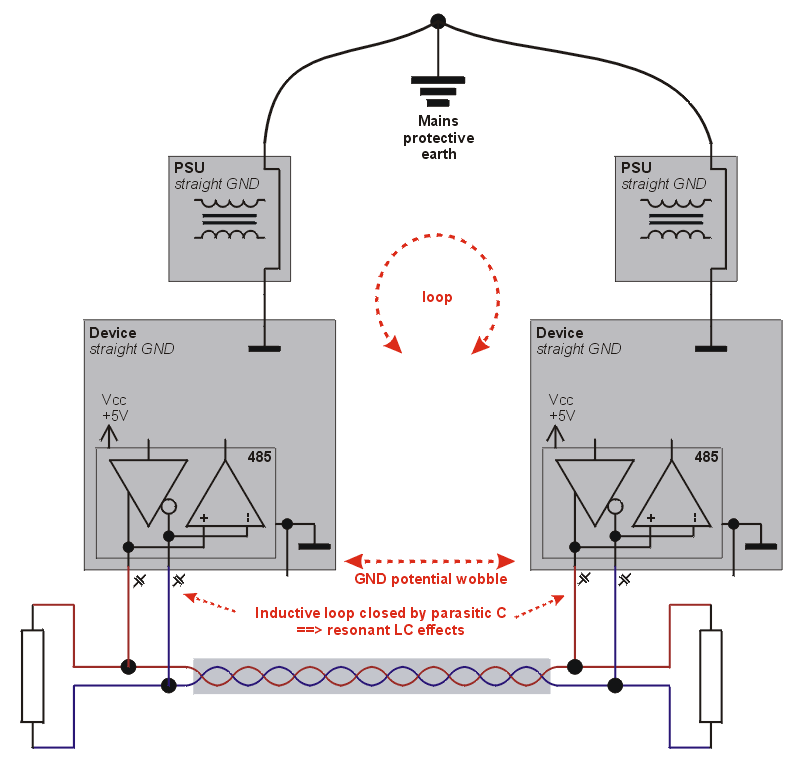
## loopey stuff - there's no explicit signal reference ground ##
An interesting aspect of the wobble is, that its wavelength is much
too long to be caused by just the 14 m of transmission line. So the resonant
frequency must result from something else.
The 14m coil of CAT5 cable and the mains ground clearly form quite a loop.
In electric terms, loop = inductance. So I figured that the wobble
was likely a sign of some LC resonance between this large loop (inductance)
and the transceivers' paracitic input capacitance (which I later determined
to be somewhere in the hundreds of pF, depending on hardware model).
Perhaps this wobble isn't outright detrimental to data integrity,
and maybe it is that way by design / per definition.
The wobble is not "tall enough" to push the differential RS485
receivers out of their common-mode operating range (approx. 0-7 V vs. GND)
with unpredictable results (generally random signal inversions / clamping).
Your general common sense tends to tell you that the longer the distances,
the bigger the loop (inductance) - the greater the chance of adverse effects.
But this appears to apply only for EMI ingress. As for the amplitude of our
resonant wobble, that is probably determined by the amplitude of the initial
common-mode edge (step-wise change of voltage), which is characteristic to the
particular bus driver, and does not depend on line length / line+GND loop
dimensions (inductance). The line+gnd loop dimensions do affect the resonant
frequency and Q of the wobble (= duration of the wobble) - but as there is no
periodic addition of energy to the "resonator", the amplitude can only decline
after the initial edge.
Still the wobble is a pretty ugly sight, and it indicates sensitivity to EMI ingress
into the "ground return path".
So, how do we suppress that resonant loop? The answer is that we need to provide a dedicated "signal reference ground" conductor, as closely aligned to the payload twisted pair as possible, in order to minimize the square of the resulting loop (to minimize its inductance). The reference ground is really a companion signal to the balanced twisted pair, helping to keep the individual nodes' transceivers "within the ballpark" of DC operating range. By minimizing the loop square, we minimize all sorts of "interference" offsetting the reference ground from the local optimum for each and every node.
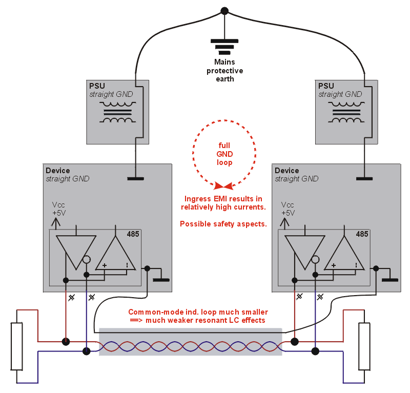
## explicit signal reference ground, at the cost of a solid ground loop ##
In my example, I just used another pair in the CAT5 cable for a reference ground. I connected the two conductors in parallel to avoid possible RF effects in the pair. I connected the ground at both nodes of interest straight to the relevant earth (I didn't install a "separation resistor") - so the grounds actually formed a hard ground loop (closed across the power supplies and mains earth), which traditionally is another big thing to avoid. Yet the effect of this grounding was profoundly positive - behold the whole second column in the "table of plots".
The ultimate right way around the loopy grounds problem is ground isolation - either at the PSU, or within the device, perhaps preferably at the RS485 port. This scenario is not depicted in my oscillograms (was not an option in my case - money always first, let alone the added complexity). Check the galvanic "detour #2" for further notes about galvanic isolation in the context of RS485.
My train of thought went in a different direction though. Note that on the
first "grounded" oscillogram,
there is still a noticeable common-mode glitch with a resonant fade-out.
The common-mode loop square is clearly smaller now, so the resonant frequency is
higher and the oscillations fade out faster. Still it was making me wonder,
how much of this is due to LC resonance, and how much could be due to an
open-ended transmission line reflection (common mode).
Take a look at the relevant "TX OFF" plot.
That's where both drivers (+/- or A/B) should "let go" of the line. Given how
the balanced driver is wired, this "line release" produces a significant
common-mode edge.

## composite 3wire transmission line (diff-mode and common-mode impedance components)##
The ground conductor (pair), following the live balanced pair in the same sheath, still comprises some "loop inductance" with the pair. But from a different perspective, it also comprises another transmission line. The balanced pair itself is a differential-mode transmission line. The balanced pair against the ground conductor (pair in my case) conceptually comprise another, common-mode transmission line. You can also think about them as a single, three-wire transmission line, with a differential-mode and common-mode component (aspect). And, just like the differential-mode TML should be terminated to prevent diff-mode reflections, the common-mode TML should also be terminated, to minimize common-mode reflections. Now how do we go about that?
If you really care this much about your transmission line :-) ,
the first thing you need to know is the common mode and diff mode impedance.
If you don't know the figures for your cable, you can measure them.
For many basic-performance twisted-pair cables, the vendor's datasheet
doesn't even give you the differential-mode nominal impedance of each pair.
And, even if the diff-mode impedance is given, the common-mode impedance is
never mentioned (on high-performance STP cables, you can hazard a guess - see below).
For unshielded TP cables, it's indeed not very fruitful or sane to ask about
the impedance between pairs :-)
Anyway you can measure the impedances if you need to know - my favourite tool
is a reflectometer. You pulse one end of the cable, terminate the other,
and watch at the generator for a far-end reflection. If there's no reflection,
your TML is terminated correctly (the resistor value is right).
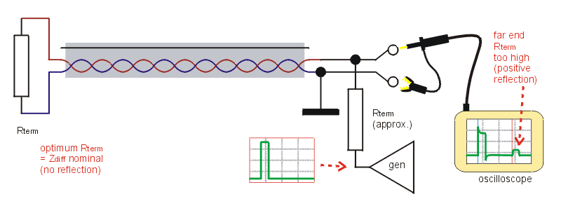
## differential mode impedance measurement ##
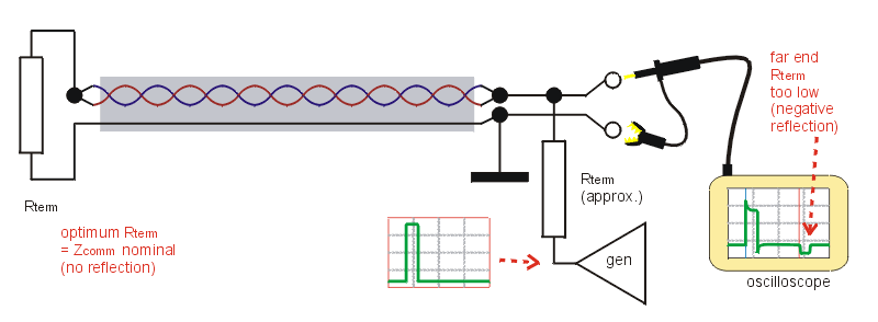
## common mode impedance measurement ##
A few notes on the measurement setup:
Once you know the impedances, you need to use an appropriate resistor
network to terminate the 3wire line. That's right, a "network" - how else
would you want to terminate the live pair conductors against each other,
and at the same time terminate both the live pair conductors against
the reference ground conductor?
In a general case, on a cable with a "poorly defined" reference ground conductor,
the common-mode impedance will be on par or maybe greater than the diff-mode
impedance in the balanced pair. Such as, in my case, both Zcomm and Zdiff were 100 ohms.
You need to design a resistive circuit, that properly terminates both the diff-mode
and the common-mode part of impedance.
Essentially you need three resistors and they can be connected in two different topologies:
a star or a triangle ("T" vs. "delta").

## three-wire termination: star vs. triangle ##
The math is fairly basic.


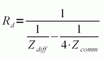

Perhaps one more touch is appropriate: AC-only coupling of the common-mode termination
("DC decoupling" ;-).
The RS485 transceivers are balanced, but work with a permanent DC offset of something
over 2 Volts. The basic resistive-only termination of the common-mode component would
increase stress on the drivers (heat dissipation), and would hamper attempts at
DC biasing (details of which will be discussed below). Note that with a good-quality
STP cable,
Zcomm = Zdiff / 4
For a quality cable with Zdiff = 120 Ω, Zcomm = 30 Ω.
This "phenomenon" will be discussed below, in the paragraph on my experience with CAT7.
2V / 30 Ω = 70 mA of additional load - that's quite a lot.

## three-wire termination, common-mode AC-coupled by capacitors ##
The easiest way to AC-couple (DC-decouple) the common-mode terminator is by adding an appropriate-sized
capacitor. What size is appropriate? Note that the "RC timing constant" (Zcomm * C)
of the terminator must correspond to the round-trip delay on the transmission line. The capacitor
should have enough capacity to absorb the energy, that can be loaded onto the TML during the
"propagation round-trip time". In other words, the longer the cable, the bigger the capacitor
required. Given an open-space vacuum speed of light of 3 * 108 m/s
and a typical "contraction coefficient" of around 0.6 to 0.7, a round-trip time
can be simply estimated as
1 m = 10 ns
or 10 cm/ns (which also happens to be my favourite reflectoprobe formula :-)
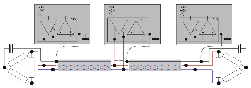
## three-wire termination with delta's at both ends, common mode AC-coupled ##
In practice in my lab experiments, I just used some 10uF ceramic caps that I happen to have
in a drawer (blocking caps from a scrapped motherboard). Combined with a Zcomm of 100 Ω,
these produce a timing constant of 1 ms - that would theoretically cover 100 km of cable :-)
so it's apparently quite an overkill for my 14m cable. Worked just fine for me anyway :-)
The timing constant corresponds to about 1 character at 9600, as can be seen on the overview
scope screenshot for CAT7 - note the upward slope.
Perhaps more importantly, note how the upgrade from "basic termination + reg gnd"
to the "DC-decoupled delta" further suppressed the wobbling between columns 2 and 3
in the table of waveforms above (use the schematics in table header as a guide).
The next thing I tried, in my parade of imperfect solutions, was to add DC biasing resistors
(as per the excellent Circuit Cellar articles) and watch the effect on scope traces.
I upgraded my Delta at the master node with the suggested 560Ω pull-up/pull-down
resistors. Actually I even re-calculated the delta itself (for the master node),
to compensate for the added resistors, to keep the Zdiff and Zcomm
precisely matched = terminated.
Note that conceptually the termination should happen at the end of the TML (there are
two of them) and is in no way correlated to the actual location of the fieldbus protocol
master (or any other bus node for that matter). There can even be a section of transmission
line with no further nodes attached, just a terminator at the free end. In my case, it just
so happend that the RS485 master was located as a "terminal node" on the bus, and it was
convenient to take +5V from the master device (rather than set up a separate power supply).
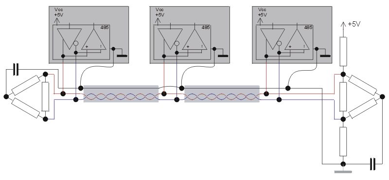
## three-wire termination, common-mode AC-coupled by capacitors, DC-biased ##
The result was somewhat surprising: the wobble has actually increased a bit,
compared to the previously unbiased delta terminator. Perhaps the matching got slightly
worse.
But the biasing resistors are not about termination - they serve a different
purpose, which is also very important: they keep the line at the recommended voltage
levels in inactive state, thus keeping the receivers happy all the time,
while at the same time reducing the common-mode "kicks" upon TX_on and TX_off.
The biasing also improves noise immunity by gently pushing the line slightly
further upwards from the decisive treshold for log.0 (-200 mV differential).
I really started my final experiment with CAT7 S/STP by checking the common
mode impedance of the signal pair against its shielding.
The scope was set for 1 GSps (highest resolution available),
the reflectometer probe (pulse generator) was jumpered for 50 Ω
output impedance (lowest available), the signal pair and shield
wired for common mode measurement, and the line was experimentally
terminated by 33 Ω (common mode, single resistor).
You can see the resulting waveform below. The section of cable was about
25m long (judging by the scope screenshot) and initially was coiled
on the table (coil diameter about 30 cm).
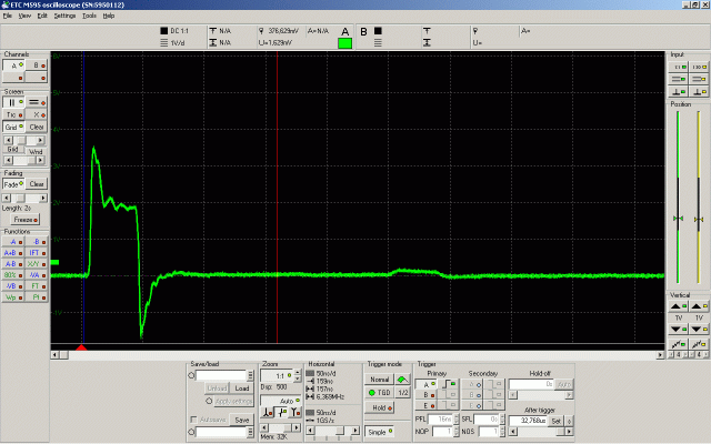
## reflectoprobe plot, CAT7 STP, common mode, terminated by 33 Ω ##
Clearly the termination resistor of 33 Ω is still a tad too high,
there is a positive reflection at the far end. It seems that the common-mode
impedance for the 100 Ω cable (differential impedance of each pair)
is around 25 Ω. That would seem to match a train of thought saying
that if the differential-mode impedance of a shielded twisted pair
is 100 Ω, the impedance of a single wire (from the pair)
against the common ground is half that (= 50 Ω),
and thus the two wires forming a twisted pair, if hooked up in
parallel and measured against the common shield ground,
exhibit half their individual impedance, i.e. a quarter of the
nominal differential impedance of the shielded twisted pair.
(Oops. Is it really that simple? The chapter on odd+even impedance modes
at microwaves101 suggest a math model that's yet more complex. Mine may
be a good enough approximation.)
The one thing in the graph that I don't completely understand is the local-end
overshooting at the pulse edges. I used to think they were a sign of inter-turn
coupling when the cable was coiled on the lab table, but the glitches are there
even if I unwind the cable and spread it throughout the room. My current hypothesis
is that the pulse could be a sign of local-end impedance mismatch. The glitch,
which corresponds to maybe 10 ns (i.e. approx. 1 m of cable), indicates after what time
/ propagation distance the cable's own impedance really kicks in. And, it may be related
to the cable's characteristic available bandwidth (cutoff frequency).
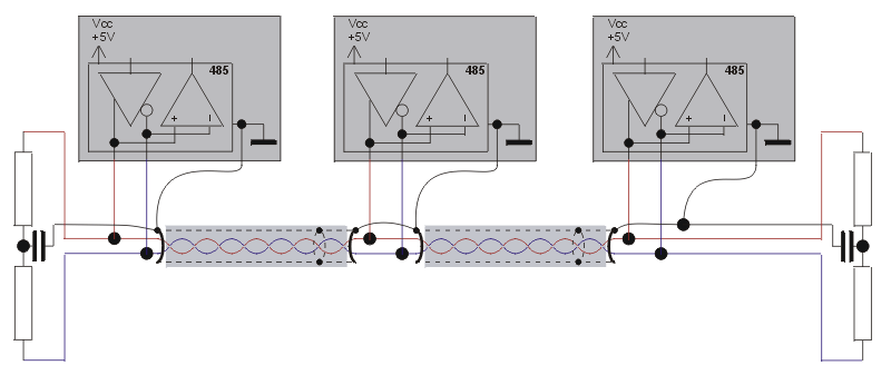
## quality STP cable, three-wire termination, common-mode AC-coupled by capacitors ##
Note that due to the quality shielding, which makes the CAT7 STP impedances act
precisely according to the serial/parallel connection math, the 3wire terminator
is reduced to 2 resistors (+1 capacitor for common-mode AC-coupling). In this case,
each of the two resistors is calculated as
R = Zdiff / 2 = Zcomm * 2
Zcomm = Zdiff / 4
Common wisdom says that RS485 runs over just about anything - but let's see what's available, if you want to make your transceivers happy cabling-wise. Especially at higher baud rates and longer distances, the choice of cable can make a big difference.
The general rules are:
Some examples of interesting cables:
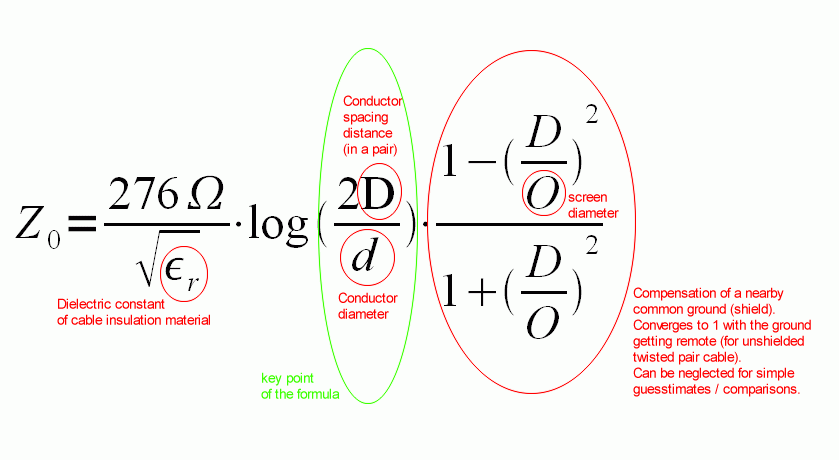
## balanced pair cabling impedance formula ##
The ultimate right way around the loopy grounds problem is ground isolation - either at the PSU, or within the device, perhaps preferably at the RS485 port - so that the RS485 bus can have its own reference ground, yet the case of every device can be bolted down to the mains protective earth.
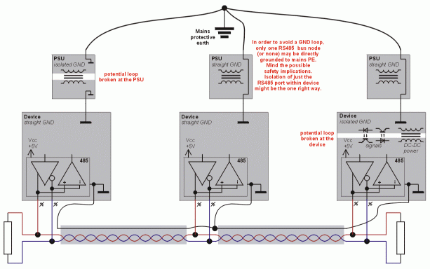
## explicit signal reference ground, GND loop avoided by isolation - click for a hi-res picture ##
There are small devices (I/O modules) that have the I/O side isolated from the rest, so that the RS485 port shares ground with the DC PSU input (the terminal labeled "24V DC PSU GND" can be used as signal reference ground). This is (almost) no problem as long as the power is distributed along with the bus signals (note that it's inappropriate for other reasons to daisy-chain power distribution cabling just like the RS485 signals). It may become a problem when you need to power the IO gadget from a local source of power, that is not earth-isolated.
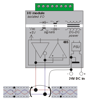
## IO module = RS485 node, with IO terminals isolated ##
Devices with a properly galv.isolated RS485 port (isolated from PSU input) theoretically don't need a reference ground, and can work with the bus using just some weak internal biasing resistors. There are devices that actually have such a properly isolated RS485 transceiver and DO NOT have a signal ground terminal. (Which may bring compatibility problems with other devices on the bus, if you don't provide external strong bias - read on for details.) In such cases, the choice not to provide a reference ground terminal (and rely on internal resistive biasing) is a matter of how much you trust your "miniature solid-state DC/DC converter" that it doesn't have parasitic capacitive coupling from the primary to secondary side (note that the primary is switched at some RF frequency). It's always better to have a reference ground terminal. It may even be a good idea to hack your device to add one :-)
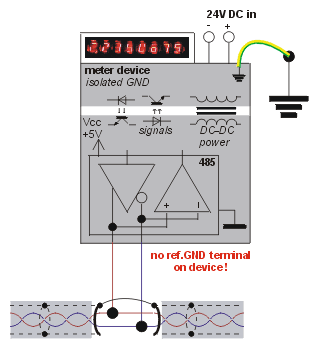
## RS485 node with isolated RS485 port, no reference ground ##
There are devices boasting a so-called "tri-galvanic" isolation - such as async modems or RS232/485 converters. When you hear that buzzword for the fist time, you will likely imagine three neat isolation gaps, surrounding the three ports (local data port, the longer-haul line interface, and the power input). But actually there are only two gaps - two gaps are enough to make the three ports isolated from each other.
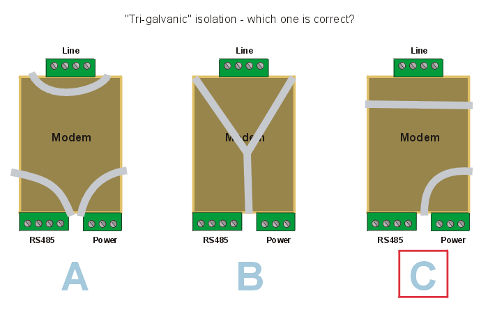
## Tri-galvanic isolation - the basic idea ##
And, the gaps tend to follow the essential premise of "least effort = least cost",
conveniently making use of components that "have to be there anyway".
The modem's PSU is typically a switch-mode module, with a relatively high
voltage at the primary side, so it already tends to contain a transformer of some sort.
You only need to make sure that the feedback from the secondary to the primary
side goes through an opto-coupler (or is derived by an additional winding on the trafo,
which is perhaps less precise). So that's the first gap - easy money.
Next, PSTN/LL modems tend to have a signal transformer (or two) as part of the line interface
- to adapt the old-style 48V/600Ω telephone circuitry to the modern
semiconductors running at or below 5V. If the modem allows for PSTN operation,
it also needs a relay contact that serves as a "phone hook switch" - so that the line
can be cut away from the signal trafo when on-hook (central office detects
a high loop impedance = phone hung up on the line) and also so that the incoming
ringing voltage of ~200V AC doesn't reach the signal transformer. The hot side
of the line interface doesn't even need a power supply.
That way, the local data inteface (232 or 485) ends up being directly connected
to the "brain" of the modem - the processor chip(s).
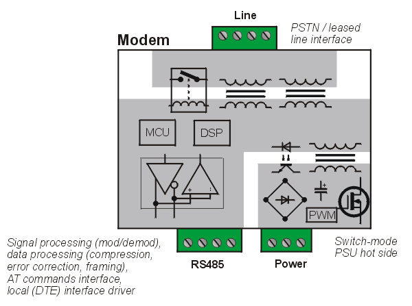
## Tri-galvanic isolation - in a bit more detail (PSTN+LL modem example) ##
In other types of communication gadgets, say a 232-to-485 converter, both the local (232) part and the long-reach (485) part may have to be powered somehow, usually by a miniature monolithic DC-DC converter. And the signal tends to be transferred by a necessary number of opto-couplers. The local 232 port will likely remain un-isolated from the converter's MCU, if there is any.
Wiring as suggested by the standard
In reality, the choice of whether or not to equip your bus with earth-isolated nodes is always a matter of money. Earth isolation is expensive, may require purchasing of additional isolated PSU's (where you already have a grounded PSU from the vendor), or purchasing of addon isolated bus transceivers (when you already have a non-isolated port on your device, chosen for other reasons).
Galvanic isolation is not a part of the RS485 spec. Perhaps that's one of the ugly compromises (price-driven) embedded in the spec, as mentioned by the Circuit Cellar articles :-) The bus is *intended* to be operated in troublesome grounding topologies, with maybe a shrug of your shoulders.
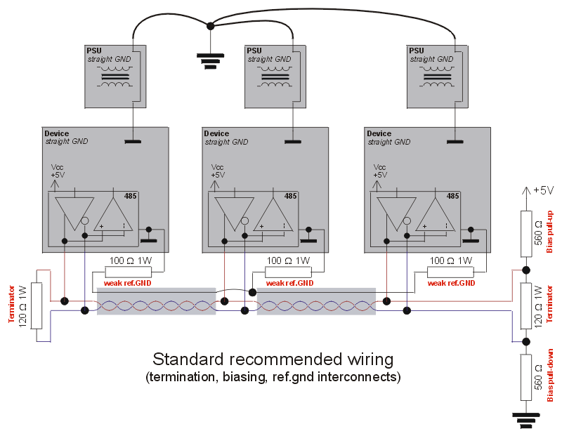
## Wiring suggested by the spec (re-drawing from the Circuit Cellar PDF) ##
In the sketch above, I'd like you to note three points:
If you look at the "biasing divider" (2x 560 Ω in series),
combined with the terminators (2x 120 Ω (typical) in parallel),
it's clear that it targets an idle voltage difference of around 1/20th
of +5V, i.e. around 250 mV differential between the + and - conductors.
And, that difference is centered between +5V and signal reference ground,
i.e. it can be written as 2.5V +/- 125 mV. The small voltage gradient is
intended to improve noise immunity of the idle bus, as 200 mV differential
is the sensitivity treshold of the bus receivers (upper toggling point of
their built-in hysteresis).
The impact of the biasing divider, if placed at TML end (= combined with a terminator),
on differential AC termination resistance, is arguably negligible (on the order of 10%)
- you could compensate that influence by increasing the terminator resistance a bit
(to 133 Ohms), but it's hardly worth the bother.
Unlike the terminator, the biasing divider does not have to be placed strictly
at the end of the bus. E.g., if you have a master node someplace in the middle
of the transmission line (with a convenient +5V terminal), and terminators
at the ends of the TML, you can place the two 560Ω biasing resistors
at the master node, while keeping the terminators at the TML ends... in DC biasing
terms, this setup is equivalent to biasing at either of the terminators.
It doesn't even have to be a master node - the biasing node can just as well
be a protocol slave, or the biasing resistors can be added someplace halfway
between the nodes on a bare transmission line.
The one thing that's amazing about RS485, is its great tolerance to the cabling used.
The balanced receiver sensitivity treshold is high enough that in many
scenarios, ingress EMI is not an issue (some point out that RS485 is more immune than CAN).
Even lack of any termination is often tolerated just fine.
The usual transfer rates are just so low, that bit length is several times
(orders of magnitude, rather) greater than the transmission-line round-trip.
Thus the open-end reflections don't matter much. The baud rate essentially
means DC to the cabling.
Common-mode noise (reference ground wobbling) is often tolerated as well,
at even surprising levels (you never get to know, until you plug in a scope).
The sensitivity treshold and hysteresis in the receiver certainly play a role.
Besides, the UARTs usually sample the input waveform somewhere halfway though
the bit duration - thus, some fuzz about the edges doesn't matter much.
In the aforementioned customer trouble case, there were actually several
problems combined.
In my lab, I noticed a weird problem somewhere in the UART or Windows,
not sure exactly where (8th bit in every character flipping on its own,
on a string of equal characters) - initially it got my whole attention,
but turned out to be a rare apparition, difficult to reproduce.
So, after some cabling exercises in the lab, I decided to pay a visit
to the customer, to see with my own scope exactly what was going on.
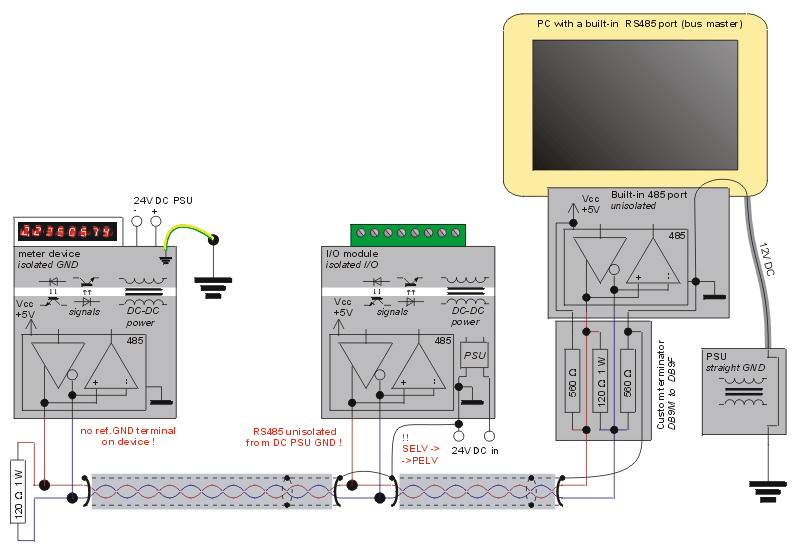
## Actual schematic in a customer case - final version, working fine ##
The customer had my culprit PC connected to just two devices
(RS485 slaves): an I/O module (not our hardware) and a meter device
- for a total of three nodes, from three different manufacturers.
In their wiring, the PC would talk just fine if only the I/O module
was connected, or if only the meter was connected.
If both the meter and the I/O module got connected, the data reading
loop would stop, and only give another retry every 20 seconds
(in vain). The only way to make them talk, was to connect exactly
one terminator (plain 120Ω resistor) - not two.
Besides the culprit master PC, we had about three different
RS485 converters (232 and USB based) some of which worked fine
in the original topology, others had further requirements :-)
A key argument of the customer was: hey it works just fine from
my laptop (over a USB/485 dongle) and it doesn't work with your
embedded PC, how come?
So I started my debugging. I ordered my steps by "layers of functionality"
and also by convenience (try the simple things first, leave time-consuming
stuff for the last resort).
First of all I verified, that the RS485 transceiver is essentially alive,
that both TX and RX work (using another converter).
Next, I mapped their transmission line. It consisted of about 4 sections
of cabling (Draka JAMAK - new to me at the time), connected together
at device terminals and an additional junction or two... Surprisingly,
there were no significant stubs (dead ends) in the topology, the bus
was fairly linear. One important aspect though: the shielding was
discontinuous (not interconnected at the ends of cable sections)
- the customer said he tried connecting the grounds and it didn't work.
The PC was directly grounded, the meter had a fully isolated RS485 port
(without a ref.ground), the IO module had an isolated PSU.
That's when I reached for my scope, and I tried watching the bus
at the I/O module, against its reference ground.
Surprisingly, there wasn't much common-mode wobble (reflections). There was some
"interference" though - and it was common mode. So the first thing
I prescribed, was to properly interconnect all the reference grounds
available. Which essentially meant twisting all the shields together
and connecting them to the master PC and the I/O module's power GND
(same as its RS485 ref.GND). The meter did not have a ref.GND terminal,
nothing to connect there.
That got rid of the common mode "PSU noise", clearly caused by the lack
of a common reference ground.
The bus still didn't work. ("But it works from my laptop, see?" - with a polite grin)
So I let the SCADA software crank away, to show me some traffic,
and tweaked the scope a bit - looked at the fuzz around bit edges,
possible interference, differential mode, common mode.
I added a proper second terminator - to no avail.
I also noticed that the meter injected some weird EMI,
if someone was talking to it on its service port
(unrelated to my bus). So we unplugged the service port,
and the bus got clear of that EMI. But it still didn't work.
By now the signal was really nice and clean, with only small
common-mode glitches on the edges (insignificant).
I could clearly see a request+response exchange,
but the master probably didn't like what he got back.
I also tried to implement proper termination, according to the RF
rules of thumb. So I measured the cable's impedace figures:
70 Ω diff-mode and about 17 Ω common-mode.
I followed those values and attached a capacitor-coupled
"diff+common" terminator. Unfortunately, the bus behaved even
worse than with the single 120Ω terminator. On the scope
I could see that the pulse shapes indeed got cleaner,
but at the same time the pulse amplitude dropped quite a lot,
and the transceivers probably didn't like that side-effect.
My explanation is that the RS485 bus drivers' output impedance
is optimized (matched) for the typical 120Ω transmission line
(the driver's output impedance should actually be half that value,
because the driver feeds two sections of the TML in parallel),
and if a lower impedance transmission line is attached to the driver,
the drivers' output sags accordingly.
This in turn means that the drivers' heat dissipation increases
significantly (more current and a greater voltage drop across the
output transistors), which is certainly a safety risk.
It also means that the transmission loses some of its "attenuation
budget", because the signal amplitude gets closer to the receivers'
nominal voltage sensitivity (the signal gets attenuated
right at the driver's output).
The morale for me is that, for short sections of cabling,
even if you don't have a 120Ω cable, you should still use
120Ω terminators, because it's more important to please
the active transceivers, than to correctly terminate the transmission
line. At short distances, the TML's wobbling does less harm
than a DC impairment. To the RF purist it's a shameful tradeoff,
to an industrial control practitioner it's quite a no-brainer.
If your cabling is not the super-short no-brainer anymore,
i.e. the length transposed to round trip time gets close to
maybe 10% of the data bit length, you should get a proper cable
in the first place (with the right impedance and a low RF attenuation),
so that you can terminate the transmission line properly,
without hampering the tranceivers' DC operating conditions.
So there I was, with the 120Ω terminators back in place,
and the bus didn't quite work, despite the nice-looking scope traces.
The one thing that caught my eye was the fact that, looking at
the pair as two signals against common ref.ground (two traces
on a dual-channel scope), responses from the I/O module were centered
around 2.5V (= proper DC bias), whereas responses from the meter
were centered around 0V, so that both pins in the signal pair
went significantly below 0 at times. Clearly owing to the
perfect isolation of the meter's RS485 port,
combined with the lack of a reference ground terminal.
The bus did indeed swiftly return to 0V when idle.
Which ultimately prompted me to add the two 560Ω
biasing resistors.
My embedded PC has an option to attach a +5V or +12V
PSU rail to pin 9 in the COM port (which can otherwise
be jumpered for RS232/422/485), instead of the standard
function of a "ring indicator" input. This is very convenient
for the biasing function.
Voila, THE BUS STARTED TO WORK! From that moment, the topology
just kept working no matter what. No matter what devices / bus converters
we attached, no matter how exactly the ref.gnd was interconnected
(as long as it was interconnected somehow).
We deployed that wiring on several sites. Later on we did clear a couple
unrelated errors and misconfigurations in the devices and software,
but the bus has always been wired in this way.

## pass-through terminator plug with biasing, powered by the host PC via pin 9 ##
To simplify the wiring, and to make use of the cables+connectors already in place (installed at the sites), we decided to encapsulate the biasing network into a "pass-through terminator plug". The three resistors fit within the standard double-ended DB9 connector cover.
The Circuit Cellar has some excellent articles on the topic:
http://www.embeddedsys.com/subpages/resources/images/documents/microsys_art_RS485.pdf
http://www.circuitcellar.com/library/ccofeature/perrin0799/index.asp
Even and odd mode impedances at Microwaves101.com:
http://www.microwaves101.com/encyclopedia/evenodd.cfm