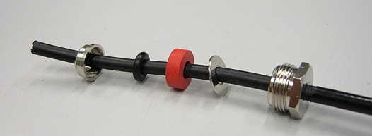
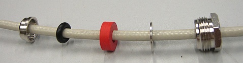
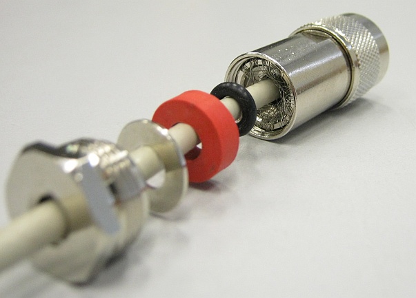
First of all, slide the tightening nut and the washers on the cable,
ordered as seen in the picture.
With this connector model, the final slanted washer is big enough to slide
over the cable's outer sheath.
The red rubber seal is an original from Shallin, the black O-ring is an upgrade by FCCPS :-)
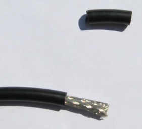
After you've slid the washers on, strip about 15-17 mm of the cable's outer sheath
(it's 15 mm in the photoes).
Be careful not to cut into the woven shield/braid, you're going to need its strands later,
preferably intact.
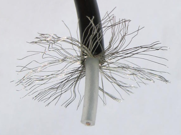
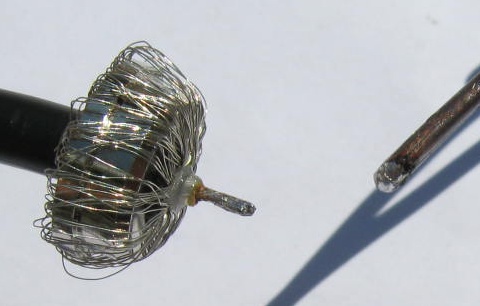
Spread the strands of the woven shield/braid.
Slide the slanted washer forward to the braid strands
and wrap the strands back around the slanted washer.
Bend the strands all the way under the flange of the washer.
Don't worry if the strand ends don't align under the flange
very neatly, the O-ring will sort them out later on.
Strip the dielectric. This inner dielectric insulation should remain
about 1 mm longer than the outer sheath. Next, you will need to
trim (shorten) the center conductor. There are actually about three
ways of how to do it:
The hole inside the center pin is about 6 mm deep.
I.e., the tin-soaken trimmed conductor should be about 5-6 mm long.
If you drop a grain of rosin into the hole in the center pin,
it helps the tin to adhere. Insert the tin-soaken conductor into
the center pin thus prepared.
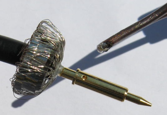
Next, solder the pin on the conductor. Heat up the pin with the iron,
perhaps add a bit of tin (solder) into the pin through the sideways
hole - not much, it should not leak out of the pin through the hole,
it would create a droplet, which would fuse with the shielding wires...
Another approach is, that you first apply some tin on the inner
surface of the hole in the pin - perhaps leave a small droplet
inside. Then, while heating the pin up, you slide the conductor
into the molten tin in the hole. Perhaps the best way to go about this
is to gently clutch the pin (by its tip) vertically in a vice,
with the center hole facing up, drop a small bit of tin inside,
and then insert the conductor (while still heating up the pin
from outside).
In order to better heat up the pin, you can improve its thermal contact
with the iron by smearing some tin deliberately behind the "flange"
of the pin (where it won't hamper the pin's insertion into connector body).
A drop of tin conducts heat better than air. If you overdose it a bit,
you can later scratch the surplus tin off with a knife or a needle file.
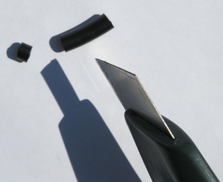
With this particular connector model, consider a small final touch:
you can secure the "narrow pin heel behind the flange" against
contact with the shielding conductors by sliding a 4mm length
of the stripped cable's outer sheath over the critical place.
Note: while this is okay with the soft RG58, you should probably
refrain from using the rigid PE outer sheath of the H1555 / RF240
in this way (you could even damage the connector internals).
Consider using some heat-shrinkable electrician's sleeve instead.
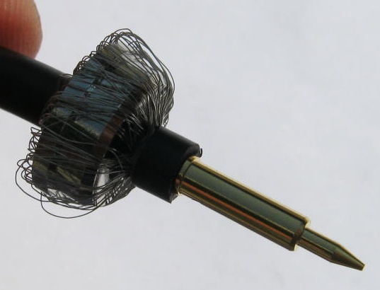
And this is what the 4mm addon insulation looks like, on the pin.
Finally, slide the prepared internals into the connector body,
slide in the washers and tighten the nut.
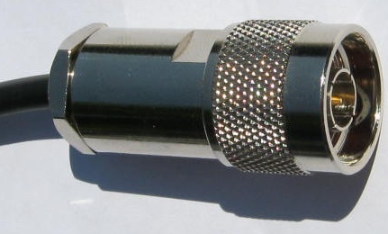
And this is the final result.
Finally, check the assembled cabling for short circuits! (between the center conductor and the shield)